
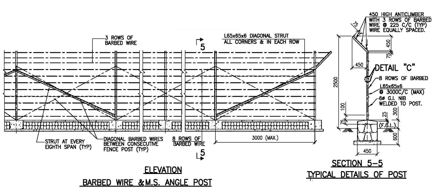
Fencing Detail Drawing Requirements
To create a comprehensive fencing detail drawing, ensure the following components and details are included:
1. Plan View
- Show the layout of the fence, including:
- Total length of the fence.
- Location of posts (spacing, corner posts, and gate posts).
- Alignment with property boundaries or site limits.
- Gate locations and dimensions.

2. Elevation View
- Display the height of the fence above the ground.
- Indicate:
- Fence material (chain link, barbed wire, panels, etc.).
- Number of wires or panels.
- Position of hooks or clamps for wire fixing.
- Post spacing and height distribution.
3. Material Specifications
- Specify materials used, such as:
- Concrete grade (e.g., M20 or M25).
- Steel reinforcement (diameter and type).
- Fencing material (chain link, barbed wire, etc.).
- Protective coatings (paint, galvanization).
4. Connection Details
- Hooks or clamps for attaching the fence material.
- Fastening methods (bolts, welding, or ties).
- Joint details for corner and gate posts.
5. Notes and Standards
- Mention relevant codes and standards, e.g., IS 456, IS 1786.
- Include any additional instructions for installation and curing.

Sample Drawing Description
A drawing that includes:
- RCC fence post elevation with reinforcement details.
- Foundation detail with dimensions.
- Hook positions for fencing wires.
- Plan view of post alignment and spacing.
Steel Fencing with Barbed Wire: Codal Requirements
Below are the general codal requirements for designing and constructing steel fencing with barbed wire as per Indian and international standards:
1. Indian Standards (IS Codes):
- IS 280:2006
- Specifies the requirements for mild steel wire used for barbed wire.
- Minimum tensile strength: 350 MPa for the wire.
- Barbs should be made of galvanized steel wire with sharp edges.
- IS 4826:1979
- Deals with the galvanization requirements for steel fencing materials.
- Minimum zinc coating: 275 g/m² for outdoor fencing in moderate environments.
- IS 1521:1972
- Specifies tensile tests for metallic wires.
- Ensures the strength of barbed wire and fencing wires.
- IS 875 (Part 3):1987
- Covers wind load considerations for fencing in exposed areas.
- IS 16644:2018
- Provides specifications for security fencing with barbed wires.

2. International Standards
- ASTM A121-07
- Covers specifications for barbed wire, including coating and tensile properties.
- ASTM F567-14
- Details the installation guidelines for security fencing, including barbed wire.
- ISO 556:1975
- Specifies barbed wire dimensions and tolerances for standard applications.
3. General Design Requirements
- Post Spacing:
- Typically 2.5–3 meters for standard fencing.
- Height of Fencing:
- Minimum height: 1.5–2.4 meters, depending on security needs.
- Barbed Wire Configuration:
- Number of strands: 3–5.
- Spacing between strands: 150–200 mm.
- Steel Fence Posts:
- Material: Hot-rolled steel, galvanized or painted.
- Dimensions: Circular hollow sections (50 mm diameter) or angular sections (50 mm x 50 mm).
- Concrete Footing:
- Minimum size: 300 mm x 300 mm x 500 mm deep.
4. Codal Installation Guidelines
- Posts should be embedded 0.6–0.9 m below ground level for stability.
- Tensioning devices to maintain taut wires.
- Use corrosion-resistant materials or proper coatings.
Requirements for RCC Fence Posts
RCC (Reinforced Cement Concrete) posts are commonly used for durable fencing solutions. Below are the key requirements and considerations:
1. Material Requirements
- Cement: Use OPC 43/53 grade cement for strength and durability.
- Aggregate:
- Coarse Aggregate: Crushed stone with a maximum size of 20 mm.
- Fine Aggregate: Clean sand with proper grading.
- Reinforcement Steel:
- Mild steel or HYSD bars of 6 mm to 12 mm diameter depending on the design.
- Ensure rust-free steel bars.
- Water: Clean, potable water for mixing and curing.
2. Design Requirements
- Dimensions:
- Height: Typically 1.8 m to 3.0 m above ground, with 0.5 m below ground for embedding.
- Cross-section: Square (100 mm x 100 mm) or rectangular (100 mm x 150 mm), depending on the load.
- Reinforcement:
- Provide 4 longitudinal bars with lateral ties at 150 mm spacing.
- For higher loads, increase reinforcement diameter or density.
- Concrete Mix: Use M20 or M25 grade concrete for strength and durability.
3. Structural Considerations
- Load Resistance: Posts must resist:
- Wind loads.
- Tension from barbed wire or fencing material.
- Lateral loads from environmental factors.
- Spacing Between Posts: Typically 2.5 to 3.0 m depending on fence material and design.
- Foundation: Embed posts in a concrete base to ensure stability.
- Depth: Minimum 500 mm to 1000 mm depending on soil conditions.
- Width: At least 1.5 times the cross-section of the post.
4. Durability Requirements
- Cover to Reinforcement: Provide at least 20-25 mm cover to avoid corrosion.
- Curing: Cure for at least 7-14 days to achieve full strength.
- Finishing: Apply water-resistant paint or plaster for additional protection.
5. Installation Guidelines
- Alignment: Ensure proper alignment and plumb during installation.
- Foundation Filling: Compact the soil around the post to prevent tilting.
- Fencing Attachment: Use hooks, grooves, or clamps integrated into the post for attaching fencing material.
6. Standards and Codes
- IS Codes:
- IS 456:2000 for concrete design.
- IS 1786 for reinforcement bars.
- Safety: Ensure compliance with local construction regulations and safety guidelines.


- 3D HOUSE DESIGN (42)
- Auto Calculator – Civil & Structural Engineering Calculation Tools (14)
- Civil and Structural Design Calculations (89)
- Commercial Plans (9)
- East Facing House Plans (16)
- Engineering Concepts – Civil & Structural (265)
- Excel Spreadsheets (37)
- Free Downloads (55)
- House Plans (65)
- Industrial standards (113)
- North Facing House Plans (16)
- South Facing House Plans (16)
- West Facing House Plans (14)

AISC Beam to Beam Bolted Shear Connection Calculator

Canadian Beam Design Calculator | Beam Load Calculator

Australian Beam Design Calculator | Beam Load Calculator

Beam to Column Shear Connection

House Plan 30 × 28 West Facing | Ground Floor + First Floor + Second Floor | 3BHK Modern Home Design

Pile Cap Detail Drawing Free Download

Splice Details for Angles

Mordern Floor Tile Design 50+
Floor Tile…

Room Paint Calculator | Quantity and Cost Estimator

Manhole Cover Detail

Commercial House Plan with 2 Shops | East Facing
Looking for…

Circular Pipe Base Plate Design | AISC ASD Guide + PDF Download

Side Cladding Runner Details for PEB Structures

Expansion Joints in Concrete Pavements

Australian Wind Load Calculator as per AS/NZS 1170.2:2021
Australian Wind…

Wind Load Calculator as per IS 875 Part 3:2015

RCC Staircase Detail Drawing free pdf Download

Modern 35×40 House Design with Premium Front Elevation

Pipe Rack GA Drawing Layout

House Plan 30×40 West Facing | 2BHK Luxury Floor Design |
Designing a…

Bund Wall Detail Drawing for Tank Farm and Oil Storage Area

Dyke Wall Layout and Detail | Oil Tank Containment Systems |

Apartment Plan 28×32 West Facing with Modern Elevation

How to Assign LY and LZ in STAAD for Steel Structures (With and Without Bracing)

HOUSE PLAN 35 X 41 | EAST FACING |

EDG Building Power Cable Layout with MTO Guide

Septic Tank Drawing and Details

Holding Tank Detail

Rain Water Harvesting System pdf Book Download

Galvanized Gate | Design Details and Specifications Guide |

Soak Pit Details | Seepage Pit |

HOUSE PLAN 25 X 48 | SOUTH FACING |
Project Overview…

Expansion, Contraction and Construction Joints in Concrete for Civil Works

Modern 4BHK West Facing House Plan (60×50) with Pool & Luxury 3D Design

Cable Rack Structural Steel Detail and Design

RCC Shear Wall Details

RCC Column with Splice and Coupler in Reinforcement Free Download

Repair Principles for Corrosion Damaged Reinforced Concrete Structures

Civil Engineering Guide to Concrete Repair and Strengthening

Australian Code Load Combinations

Modular Kitchen | Kitchen Cabinet Design Ideas with Cost |

Bathroom Design Ideas for Modern Homes

Manhole Types and Details

Catch Basin Types and Details

Eurocode Base Plate Calculator – EN 1993-1-8

Base Plate Design Calculation AS 4100

Base Plate Design Calculator CSA A23.3

Base Plate Design Calculator ACI 318

Base Plate Design as per IS 800 2007
