
Introduction
The base plate is one of the most important structural components in a steel structure because it transfers loads from the steel pipe column to the reinforced concrete pedestal. A properly designed base plate ensures that axial compression, bending moments, shear forces, and uplift loads are safely transmitted into the foundation without exceeding the allowable stresses of the steel plate, concrete, or anchor bolts.
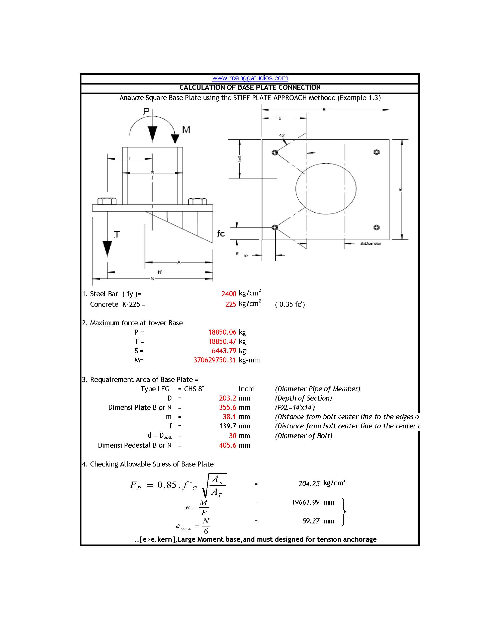
For circular hollow sections (CHS) or steel pipe columns, the AISC ASD Stiff Plate Method is widely used. This method assumes that the base plate behaves as a rigid plate while checking concrete bearing pressure, anchor bolt tension, eccentric loading, and plate bending thickness.
Design Inputs
Before starting the design, collect the following information.
Column Properties
- Pipe Outside Diameter (D)
- Pipe Wall Thickness (t)
- Steel Grade (Fy)
- Pipe Section Properties
Base Plate Details
- Plate Length (B)
- Plate Width (N)
- Plate Thickness (tₚ)
- Edge Distance (m)
- Distance from Bolt Centre to Pipe Centre (f)
Anchor Bolt Details
- Number of Bolts
- Bolt Diameter
- Bolt Grade
- Bolt Layout
- Bolt Embedment Depth
Concrete Properties
- Concrete Grade
- Concrete Compressive Strength (f’c)
- Pedestal Dimensions
Applied Loads
- Axial Compression (P)
- Uplift Force (T)
- Shear Force (V)
- Bending Moment (M)
Step 1 – Determine the Required Base Plate Area
The base plate should provide sufficient bearing area so that the concrete bearing stress remains within the allowable limit.
The allowable concrete bearing stress is calculated as:Fp=0.85fc′ApAs
Where:
- Fp = Allowable concrete bearing stress
- f’c = Concrete compressive strength
- As = Supporting concrete area
- Ap = Base plate area
Explanation
This equation increases the allowable concrete bearing pressure when the supporting concrete pedestal is larger than the base plate. The calculated bearing stress must always remain below the allowable value.
Step 2 – Check Load Eccentricity
When bending moments act on the column, the compression force shifts away from the centre of the base plate.
The eccentricity is calculated ase=PM
Where
- M = Applied bending moment
- P = Axial compression load
Explanation
The eccentricity determines how the compression force is distributed over the base plate. A higher eccentricity increases anchor bolt tension and reduces the concrete compression area.
Step 3 – Determine the Kernel Distance
The kernel distance is the maximum eccentricity that still allows the entire base plate to remain in compression.
The kernel distance isekern=6N
Where
- N = Base plate dimension in the direction of bending
Explanation


Ife≤ekern
the entire base plate remains in compression.
Ife>ekern
part of the plate lifts from the concrete and anchor bolts must resist tension.
Step 4 – Calculate the Modular Ratio
The modular ratio relates the stiffness of steel to concrete.n=EcEs
orn=57fc′Es
Where
- Es = Elastic modulus of steel
- Ec = Elastic modulus of concrete
Free PDF download for Steel Pipe Base Plate Design as per AISC ASD
The modular ratio is required for calculating concrete pressure distribution beneath the base plate.
Step 5 – Determine the Compression Zone
For eccentric loading, only part of the base plate remains in compression.
The compression width is determined usingA3+K1A2+K2A+K3=0
WhereK1=3(e−2N) K2=B6nAs(f+e) K3=−K2(2N+f)
Explanation
This cubic equation is solved iteratively to determine the width of the compression zone. The calculated value is then used to evaluate anchor bolt forces and concrete bearing stress.
Step 6 – Calculate Anchor Bolt Tension
Once the compression zone is known, the uplift force resisted by the anchor bolts is determined.T=P[(2N−3A+f)(2N−3A−e)]
Where
- T = Total anchor bolt tension
- P = Axial load
- A = Compression zone width
- f = Distance from bolt centre to pipe centre
Explanation
This equation determines the total uplift force acting on the anchor bolts. The force is then divided among the tension-side bolts for bolt design.
Step 7 – Check Concrete Bearing Stress
Concrete bearing stress beneath the compression zone is calculated asfc=Asn(2N−A+f)TA
Where
- fc = Concrete bearing stress
Explanation
The calculated bearing pressure should not exceed the allowable bearing capacity of the concrete. If it does, increase the base plate dimensions, pedestal size, or concrete strength.
Step 8 – Determine the Plate Projection
The plate projects beyond the outside diameter of the pipe and behaves like a cantilever.
The projection isb=2B−0.8D
Where
- B = Plate width
- D = Pipe outside diameter
Explanation
The cantilever projection governs the bending moment in the plate and directly influences the required plate thickness.
Step 9 – Calculate Plate Bending Moment
The bending moment acting on the cantilever portion of the plate isMPL=2fcplb2+3(fc−fcpl)b2
Where
- fcpl = Bearing pressure at the pipe face
- fc = Maximum concrete bearing stress
Explanation
This equation calculates the bending moment developed in the cantilever portion of the base plate due to concrete bearing pressure.
Step 10 – Calculate Required Section Modulus
The required section modulus isS=FbM
WhereFb=0.75Fy
Explanation
The allowable bending stress is taken as 75% of the steel yield strength under ASD provisions.
Step 11 – Calculate Required Plate Thickness
The required plate thickness istp=Fb6M
Explanation
This equation determines the minimum plate thickness required to resist bending stresses without exceeding the allowable steel stress.
Step 12 – Check the Tension Side of the Plate
The effective width is determined asr=b−m beff=r+(b−m)
The required thickness becomestp=beffFb6M
Explanation
The tension side often governs the final plate thickness because anchor bolt forces create higher bending stresses near the bolts. The larger thickness obtained from the compression-side and tension-side checks should be adopted.
Step 13 – Design Anchor Bolts
After determining the bolt tension, the anchor bolts must be checked for:
- Tensile capacity
- Shear capacity
- Combined tension and shear
- Concrete breakout strength
- Pull-out resistance
- Edge distance requirements
- Embedment length
- Washer bearing strength
Explanation
The anchor bolts must safely transfer uplift and lateral loads into the concrete foundation while satisfying the applicable design code.
Step 14 – Check Weld Design
The weld joining the pipe to the base plate should be designed to resist:
- Axial compression
- Shear force
- Bending moment
- Combined stresses
Explanation
A continuous fillet weld around the circumference of the pipe is commonly used. The weld size should be sufficient to transfer all forces from the pipe into the base plate.
Step 15 – Final Design Verification
Before finalizing the design, verify that:
- ✓ Concrete bearing stress is within allowable limits.
- ✓ Base plate dimensions are adequate.
- ✓ Plate thickness satisfies bending requirements.
- ✓ Anchor bolt tension is within allowable capacity.
- ✓ Shear transfer mechanism is adequate.
- ✓ Weld design is safe.
- ✓ Edge distances satisfy code requirements.
- ✓ Constructability and fabrication requirements are met.
Conclusion
The AISC ASD Stiff Plate Method provides a systematic procedure for designing circular pipe base plates subjected to combined axial load, bending moment, uplift, and shear. By checking concrete bearing capacity, eccentricity, compression zone, anchor bolt forces, plate bending, weld strength, and overall stability, engineers can achieve a safe, economical, and code-compliant base plate design. This method is widely used in PEB buildings, steel sheds, industrial structures, pipe racks, transmission towers, communication towers, equipment supports, and heavy steel construction, making it one of the most reliable approaches for circular steel column base connections.
- Beam to Column Shear Connection
 Introduction Beam-to-column shear connections are among the most frequently used… Read more: Beam to Column Shear Connection
 - Room Paint Calculator | Quantity and Cost Estimator
 Looking to renovate your room? Our Room Paint, Primer &… Read more: Room Paint Calculator | Quantity and Cost Estimator
 - Circular Pipe Base Plate Design | AISC ASD Guide + PDF Download
 Introduction The base plate is one of the most important… Read more: Circular Pipe Base Plate Design | AISC ASD Guide + PDF Download
 - Australian Wind Load Calculator as per AS/NZS 1170.2:2021
 Australian Wind Load Calculator | AS/NZS 1170.2:2021 Australian Wind Load… Read more: Australian Wind Load Calculator as per AS/NZS 1170.2:2021
 - Wind Load Calculator as per IS 875 Part 3:2015
 Industrial Shed Wind Load Calculator | IS 875 Part 3:2015… Read more: Wind Load Calculator as per IS 875 Part 3:2015
 - How to Assign LY and LZ in STAAD for Steel Structures (With and Without Bracing)
 🔹 What is LY and LZ? In STAAD.Pro: These define… Read more: How to Assign LY and LZ in STAAD for Steel Structures (With and Without Bracing)
 - Expansion, Contraction and Construction Joints in Concrete for Civil Works
 1. Introduction Concrete is one of the most widely used… Read more: Expansion, Contraction and Construction Joints in Concrete for Civil Works
 - Cable Rack Structural Steel Detail and Design
 Introduction Cable racks (also called cable trays or cable support… Read more: Cable Rack Structural Steel Detail and Design
 - Repair Principles for Corrosion Damaged Reinforced Concrete Structures
 Reinforced concrete is one of the most widely used construction… Read more: Repair Principles for Corrosion Damaged Reinforced Concrete Structures
 - Civil Engineering Guide to Concrete Repair and Strengthening
 Concrete is one of the most widely used construction materials… Read more: Civil Engineering Guide to Concrete Repair and Strengthening
 - Australian Code Load Combinations
 (For Steel Structures & RCC Buildings) 1. Relevant Australian Standards… Read more: Australian Code Load Combinations
 - Eurocode Base Plate Calculator – EN 1993-1-8
 Introduction Base plates are critical components in steel structures, transferring… Read more: Eurocode Base Plate Calculator – EN 1993-1-8
 - Base Plate Design Calculation AS 4100
 Introduction In structural steel design, the base plate is a… Read more: Base Plate Design Calculation AS 4100
 - Base Plate Design Calculator CSA A23.3
 Introduction Steel column base plates transfer loads from the column… Read more: Base Plate Design Calculator CSA A23.3
 - Base Plate Design Calculator ACI 318
 Introduction Designing a steel column base plate is a critical… Read more: Base Plate Design Calculator ACI 318
 - Base Plate Design as per IS 800 2007
 Introduction (Anchor Bolts Outside & Inside Column Flange) Base plates… Read more: Base Plate Design as per IS 800 2007
 - Bar Bending Schedule | BBS Calculator For Beam Column and Slab
 Managing the Bar Bending Schedule (BBS) is one of the… Read more: Bar Bending Schedule | BBS Calculator For Beam Column and Slab
 - Load Conversion & Stress Calculator | kN to kg, ton, N, MPa Online
 Load Conversion & Stress Calculator for Civil and Structural Engineers… Read more: Load Conversion & Stress Calculator | kN to kg, ton, N, MPa Online
 - Water Tank Capacity Calculator – Feet & Meter Conversion (Litres & Gallons)
 Water Tank Capacity Calculator with Unit Conversion Accurate water storage… Read more: Water Tank Capacity Calculator – Feet & Meter Conversion (Litres & Gallons)
 - Brick Wall Construction Calculator | Calculate Bricks & Cost Instantly |
 Introduction Building a brick wall requires accurate planning to avoid… Read more: Brick Wall Construction Calculator | Calculate Bricks & Cost Instantly |
 - Unit Converter – Feet, Inches, cm, mm, Yard to Meter and Vice Versa
 Length Unit Converter 🌙 Toggle Dark Mode Length Unit Converter… Read more: Unit Converter – Feet, Inches, cm, mm, Yard to Meter and Vice Versa
 - Lifting Analysis of Skid Using Spreader Beam 4-Point
 COG Shift, Moment Calculation & Sling Forces for STAAD Pro… Read more: Lifting Analysis of Skid Using Spreader Beam 4-Point
 - Base Plate Design as per IS Code | IS 800:2007 Steel Column Base |
 Introduction In steel structures, the base plate is a critical… Read more: Base Plate Design as per IS Code | IS 800:2007 Steel Column Base |
 - Wind Load Calculation IS 875 Part 3 2015
 Below is a compact, practical guide you can use on… Read more: Wind Load Calculation IS 875 Part 3 2015
 - Road Turning Radius as per IS/IRC Codes and International Standards AASHTO BS/DMRB
 1. Turning Radius as per Indian Standards (IRC/IS Codes) In… Read more: Road Turning Radius as per IS/IRC Codes and International Standards AASHTO BS/DMRB