
Introduction
In structural steel design, the base plate is a critical component that ensures the proper transfer of axial loads and moments from a column to its foundation. Accurate design of base plates with proper bolt layout is essential to prevent excessive bending, tension, or compression in steel connections.
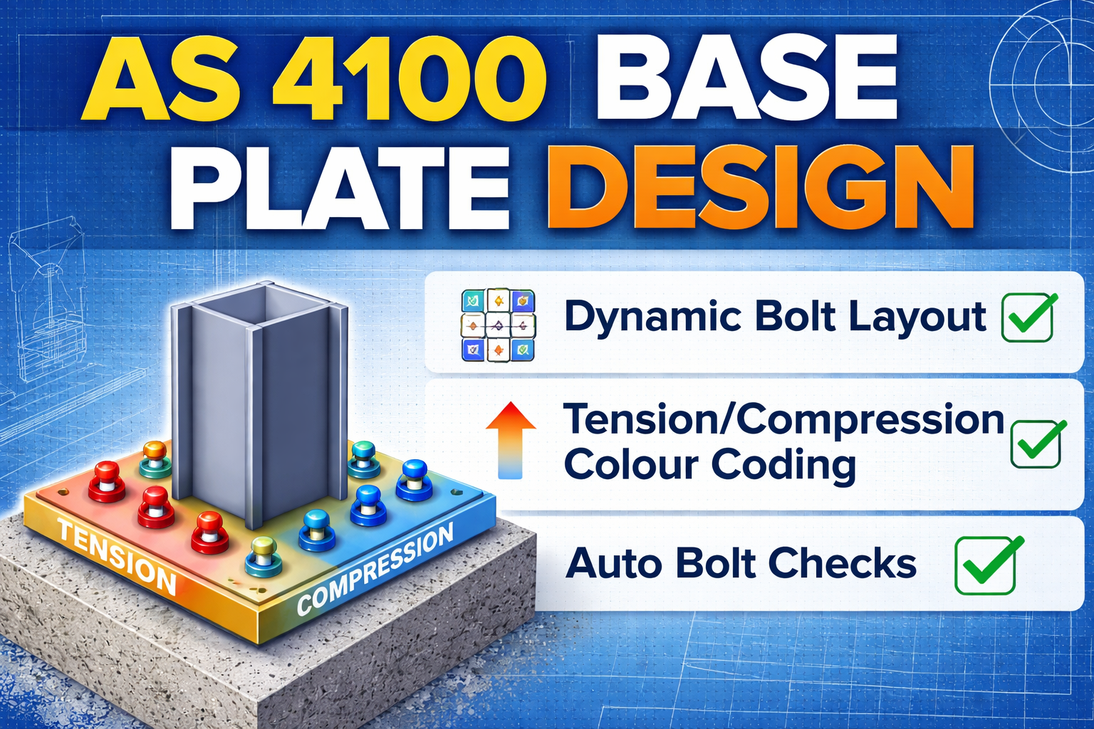
To simplify this process, our AS 4100 Base Plate Calculator offers a dynamic, interactive solution for engineers, designers, and students. It provides automatic bolt arrangement, tension/compression visualization, and detailed calculations with reference to Australian codes, all in a single, easy-to-use tool.
AS 4100 Base Plate Calculator with Bolt Layout – Metric
| Input Parameters | |
|---|---|
| Factored Axial Load N* (kN) | |
| Factored Moment M* (kN·m) | |
| Base Plate Width Bp (mm) | |
| Base Plate Length Lp (mm) | |
| Concrete Strength f′c (MPa) | |
| Plate Yield Strength fy (MPa) | |
| Anchor Bolt Type | |
| Number of Bolts n | |
| Bolt Diameter (mm) | |
| Distance from Column Face / spacing (mm) | |
| Bolt Steel Grade fu (MPa) | |
How to Use This Sheet
- Enter factored axial load (N*) and moment (M*) from structural analysis (AS/NZS 1170).
- Enter trial base plate dimensions (Bp & Lp). Adjust to satisfy concrete bearing.
- Enter material properties: concrete f′c, plate fy, bolt fu.
- Select anchor bolt option: inside or outside column, number of bolts, diameter, and distance from column.
- Results update automatically: concrete bearing, plate thickness, bolt tension, and layout diagram.
- If bolt tension exceeds capacity, suggestions for increasing bolt diameter or number are displayed.
- Use diagram to verify bolt locations relative to column face.
Codal References
- Concrete bearing: AS 3600 Clause 12
- Plate bending: AS 4100 Clause 8
- Anchor bolt tension: AS 5216
- Anchor bolt design: φb*Ab*fu per AS 5216
Disclaimer:
This Base Plate Calculator is for educational and reference purposes only. Always verify results independently and ensure designs comply with AS 4100, AS 3600, AS 5216, and project specifications.
Key Features
- Automatic Bolt Arrangement:
The tool dynamically arranges any number of bolts in a proper grid for both inside and outside column options, ensuring correct spacing and layout. - Tension & Compression Visualization:
Bolts on the tension side are highlighted in red, and bolts on the compression side in blue, helping you quickly identify stress distribution. - Detailed Step-by-Step Calculations:
The calculator provides a comprehensive breakdown of all design steps:- Base plate area
- Concrete bearing stress
- Plate thickness
- Bolt tension and capacity
- Automatic Bolt Tension Check:
Compare applied moment and axial load with bolt capacity. If tension exceeds allowable limits, the calculator suggests increasing bolt size or quantity. - Interactive Diagram:
The 2D visual layout scales dynamically to base plate size and bolt spacing. Users can easily visualize the column footprint, bolt locations, and tension/compression sides.
How to Use
- Enter the factored axial load (N*) and moment (M*) from structural analysis.
- Enter trial base plate dimensions (width and length).
- Specify material properties: concrete strength (f′c), plate yield (fy), bolt steel grade (fu).
- Choose bolt type (inside/outside column), number of bolts, diameter, and distance from column.
- The tool updates bolt layout, plate thickness, concrete bearing, and tension/compression side colors automatically.
- Review step-by-step calculations with codal references and recommendations if required.
Codal References
- Concrete bearing: AS 3600 Clause 12
- Plate bending: AS 4100 Clause 8
- Anchor bolt tension: AS 5216 Clause 4.2
- Anchor bolt design: φbAbfu per AS 5216
Benefits
- Eliminates manual errors in base plate design.
- Saves significant design time for engineers and draftsmen.
- Provides clear visualization for better decision-making.
- Fully compliant with Australian steel and concrete standards.
- Suitable for any number of bolts, column sizes, and moment directions.
Use this tool to design base plates for any steel column connection efficiently while staying fully compliant with Australian standards.
Base Plate Design as per Australian Standard (AS 4100 – Metric)
Applicable Codes
- AS 4100: Steel Structures
- AS 3600: Concrete Structures (for concrete bearing & anchors)
- AS/NZS 1170 (for actions if loads are derived)
- AS 5216 (anchor design – if detailed anchoring is required)
1. Design Inputs (Metric)
| Parameter | Symbol | Unit |
|---|---|---|
| Axial load | N∗ | kN |
| Moment | M∗ | kN·m |
| Shear | V∗ | kN |
| Column size | — | mm |
| Concrete strength | fc′ | MPa |
| Plate yield strength | fy | MPa (usually 250 MPa) |
2. Factored Actions
Use ultimate limit state (ULS) loads:N∗,M∗,V∗as per AS/NZS 1170
3. Base Plate Area (Concrete Bearing)
Design bearing pressure on concrete:
q∗=ApN∗±BpLp26M∗
Where:
- Ap=Bp×Lp (mm²)
- Bp,Lp = base plate dimensions (mm)
Allowable concrete bearing stress (AS 3600):
qult=0.85fc′
✅ Check:q∗≤0.85fc′
4. Plate Thickness Design (AS 4100)
Base plate acts as a cantilever slab projecting beyond column face.
Projection:
a=2(Bp−bc),b=2(Lp−dc)
Use the larger projection.
Bending moment per unit width:
m∗=q∗a2/2
Plate thickness:
tp≥ϕfy6m∗
Where:
- ϕ=0.9 (steel bending)
- fy=250 MPa (typical)
5. Moment & Tension Check (If Uplift Exists)
If:e=N∗M∗>6Lp
→ Tension develops → anchor bolts required
Compression block length:c=0.85fc′BpN∗
Remaining force taken by anchors.
6. Anchor Bolt Design (Overview)
Anchor tension per bolt:T∗=nzM∗−N∗c/2
Check as per AS 5216:
- Steel failure
- Concrete cone
- Pull-out
- Edge distance
7. Shear Check
Shear resisted by:
- Friction: μN∗
- Or anchor bolts / shear key
V∗≤ϕμN∗
Typical:
- μ=0.3 (steel–concrete)
- ϕ=0.8
8. Typical Material Specifications
| Item | Specification |
|---|---|
| Base plate | AS/NZS 3678 – Grade 250 |
| Anchor bolts | Property Class 8.8 |
| Grout | Non-shrink, ≥ 40 MPa |
| Concrete | ≥ 25 MPa |
9. Detailing Requirements (AS 4100)
- Minimum plate thickness: ≥ 12 mm
- Edge distance to anchor: ≥ 1.5 × bolt dia
- Plate projection: ≥ 50 mm
- Grout thickness: 20–50 mm
10. Summary Design Flow
- Apply factored loads
- Size base plate from concrete bearing
- Check eccentricity
- Design plate thickness
- Design anchors (if tension)
- Beam to Column Shear Connection
 Introduction Beam-to-column shear connections are among the most frequently used… Read more: Beam to Column Shear Connection
 - House Plan 30 × 28 West Facing | Ground Floor + First Floor + Second Floor | 3BHK Modern Home Design
 If you are searching for a compact yet luxurious West… Read more: House Plan 30 × 28 West Facing | Ground Floor + First Floor + Second Floor | 3BHK Modern Home Design
 - Pile Cap Detail Drawing Free Download
 Pile caps are one of the most important components in… Read more: Pile Cap Detail Drawing Free Download
 - Splice Details for Angles
 Steel angle sections are one of the most commonly used… Read more: Splice Details for Angles
 - Mordern Floor Tile Design 50+
 Floor Tile Design Ideas – Elevate Your Spaces with Style… Read more: Mordern Floor Tile Design 50+
 - Room Paint Calculator | Quantity and Cost Estimator
 Looking to renovate your room? Our Room Paint, Primer &… Read more: Room Paint Calculator | Quantity and Cost Estimator
 - Manhole Cover Detail
 Manhole covers are one of the most important components in… Read more: Manhole Cover Detail
 - Commercial House Plan with 2 Shops | East Facing
 Looking for a modern commercial-cum-residential building plan that generates rental… Read more: Commercial House Plan with 2 Shops | East Facing
 - Circular Pipe Base Plate Design | AISC ASD Guide + PDF Download
 Introduction The base plate is one of the most important… Read more: Circular Pipe Base Plate Design | AISC ASD Guide + PDF Download
 - Side Cladding Runner Details for PEB Structures
 Introduction Side cladding runners are one of the most important… Read more: Side Cladding Runner Details for PEB Structures
 - Expansion Joints in Concrete Pavements
 Concrete pavements are designed to withstand heavy traffic loads, temperature… Read more: Expansion Joints in Concrete Pavements
 - Australian Wind Load Calculator as per AS/NZS 1170.2:2021
 Australian Wind Load Calculator | AS/NZS 1170.2:2021 Australian Wind Load… Read more: Australian Wind Load Calculator as per AS/NZS 1170.2:2021
 - Wind Load Calculator as per IS 875 Part 3:2015
 Industrial Shed Wind Load Calculator | IS 875 Part 3:2015… Read more: Wind Load Calculator as per IS 875 Part 3:2015
 - RCC Staircase Detail Drawing free pdf Download
 Reinforced Cement Concrete (RCC) staircases are one of the most… Read more: RCC Staircase Detail Drawing free pdf Download
 - Modern 35×40 House Design with Premium Front Elevation
 Building a dream home on a 35×40 plot is one… Read more: Modern 35×40 House Design with Premium Front Elevation