

Introduction
Side cladding runners are one of the most important secondary structural members in a Pre-Engineered Building (PEB) or conventional steel shed. They support wall cladding sheets, transfer wind loads to the primary structure, maintain alignment of wall panels, and improve the overall stability of the building.
The attached drawings illustrate typical side cladding runner elevations, sag rod arrangements, runner connections, and support details commonly used in industrial sheds, warehouses, manufacturing plants, logistics centers, and commercial steel buildings.
What is a Side Cladding Runner?
A side cladding runner (also called a wall girt) is a horizontal steel member fixed between columns to support wall cladding sheets.
Main Functions
✔ Supports wall sheeting
✔ Transfers wind loads to columns
✔ Prevents sheet deflection
✔ Maintains wall alignment
✔ Provides lateral restraint
✔ Supports doors, windows, louvers, and wall accessories
Typical Components Shown in the Drawings
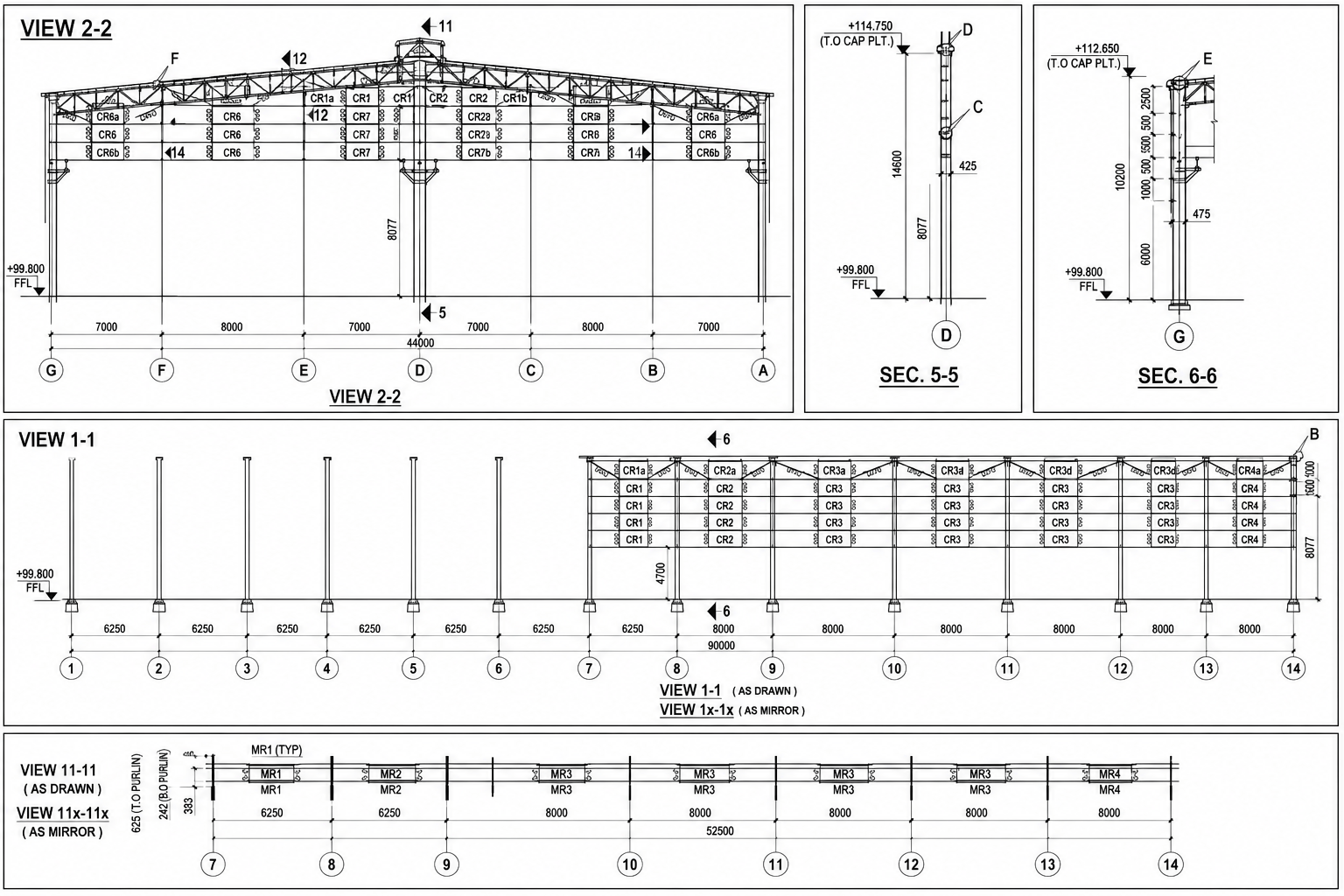
1. Side Cladding Runner (CR)
The drawings indicate multiple runner levels designated as:
- CR1
- CR2
- CR3
- CR4
- CR5
- CR6
- CR7
These runners are generally fabricated from:
- Cold-formed Z sections
- Cold-formed C sections
- Built-up light sections
Common sizes:
| Section | Typical Size |
|---|---|
| Z Girt | 200×70×20×2.0 mm |
| Z Girt | 250×75×20×2.5 mm |
| C Girt | 200×75×20×2.0 mm |
| C Girt | 250×75×20×2.5 mm |
Side Cladding Elevation Arrangement


The elevation drawing shows:
- Building length = 90 m
- Bay spacing = 6.25 m to 8.0 m
- Multiple runner levels
- Column-to-column runner supports
- Intermediate sag rod supports
- Roof-to-wall junction connections
The spacing of runners depends upon:
- Wind load
- Sheet thickness
- Building height
- Design code requirements
Sag Rod System
Purpose of Sag Rods
Sag rods reduce bending moments in runners and prevent excessive deflection.
Without sag rods:
- Runner bending increases
- Sheet vibration increases
- Fastener stress increases
With sag rods:
- Load sharing improves
- Runner span effectiveness reduces
- Overall stiffness increases
Typical Sag Rod Detail
The drawing shows:
Material
- Ø16 mm sag rod
- Threaded ends
- Nut and washer arrangement
Connection Components
- M16 bolts
- Angle cleats
- Plate washers
- Support angles
Typical Lengths
| Sag Rod Mark | Length (mm) |
|---|---|
| SR1 | 1350 |
| SR2 | 1380 |
| SR3 | 1450 |
| SR4 | 1000 |
| SR5 | 1200 |
Monitor Roof Sag Rod Detail (MSR)
The monitor roof connection detail uses a specially bent sag rod.
Advantages
- Supports monitor wall girts
- Controls vibration
- Prevents runner twisting
- Improves stability under wind loading
The detail consists of:
- Ø16 bent sag rod
- Cleat supports
- Nut and washer assembly
- Adjustable threaded ends
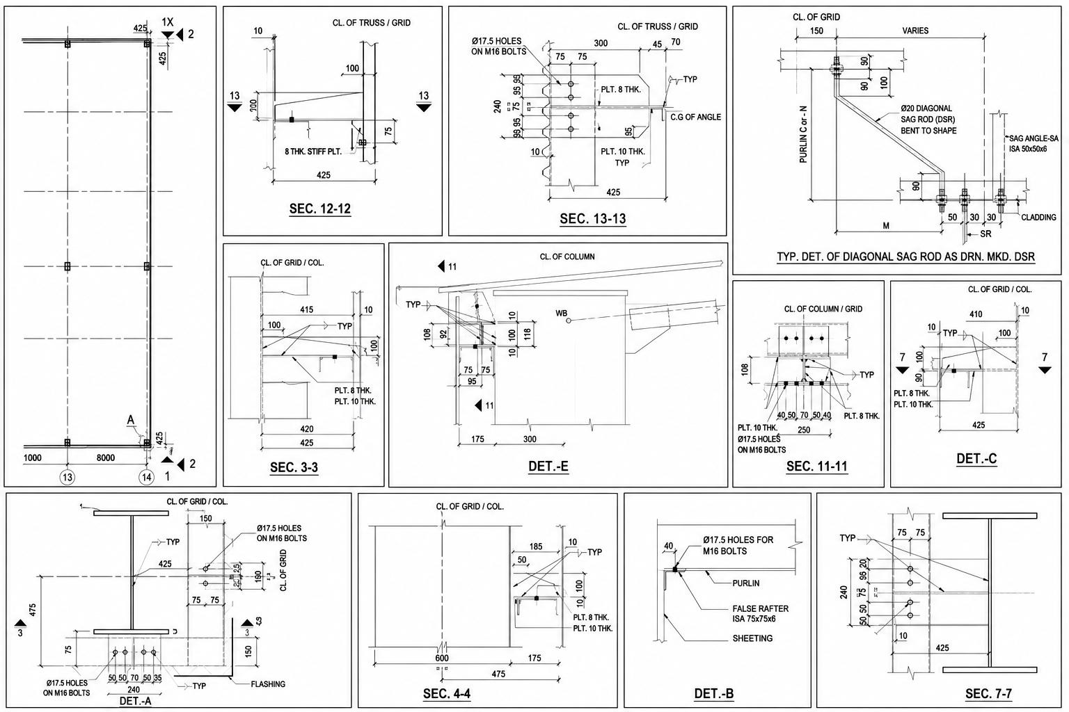
Runner Connection Details
Column Connection
The drawings show runner-to-column connections using:
- 8 mm plate cleats
- 10 mm connection plates
- M16 bolts
- Slotted erection holes
Typical arrangement:
- 2 Nos. M16 bolts
- 17.5 mm hole diameter
- Cleat welded to column flange
Connection Plate Details
Typical connection plate thickness:
| Plate Type | Thickness |
|---|---|
| Cleat Plate | 8 mm |
| Support Plate | 10 mm |
| Stiffener Plate | 8 mm |
| Angle Connection | ISA 50×50×6 |
Diagonal Sag Rod Arrangement
The attached detail shows:

Components
- Ø20 diagonal sag rod
- ISA 50×50×6 support angle
- Cladding fixing support
- M16 bolted connection
Function
Diagonal sag rods:
- Reduce runner buckling
- Improve wall stability
- Transfer lateral forces
- Reduce vibration caused by wind
Design Loads on Side Cladding Runners
Dead Load
Includes:
- Cladding sheet weight
- Fasteners
- Insulation
- Accessories
Typical value:
0.10–0.25 kN/m²
Wind Load
The governing load for wall runners.
Design according to:
- IS 875 Part 3
- MBMA
- ASCE 7
- Eurocode EN 1991
Factors considered:
- Basic wind speed
- Terrain category
- Building height
- Internal pressure
- External pressure
Runner Design Checks
The following checks are generally performed:
Strength Check
- Major axis bending
- Minor axis bending
- Combined stress
Serviceability Check
- Deflection limits
Typical limit:
L/150 to L/180
Connection Check
- Bolt shear
- Bolt bearing
- Plate bending
- Weld strength
Stability Check
- Lateral torsional buckling
- Local buckling
- Distortional buckling
Installation Procedure
Step 1
Erect primary steel columns.
Step 2
Install side wall runners.
Step 3
Align runners using temporary supports.
Step 4
Install sag rods.
Step 5
Tighten all nuts and bolts.
Step 6
Check line and level.
Step 7
Install wall cladding sheets.
Step 8
Final torque verification.
Common Site Problems
Runner Sagging
Cause:
- Missing sag rods
- Improper spacing
Sheet Oil Canning
Cause:
- Excessive runner deflection
Bolt Loosening
Cause:
- Poor tightening
- Vibration
Runner Twisting
Cause:
- Lack of bracing
Best Practices
✔ Use galvanized runners
✔ Provide sag rods at every bay
✔ Maintain proper bolt torque
✔ Use minimum M16 bolts
✔ Check wind load calculations
✔ Verify runner alignment before cladding installation
✔ Provide corrosion protection
✔ Follow approved erection drawings
Conclusion
Side cladding runners, sag rods, and connection details play a critical role in the performance of PEB and steel shed structures. Properly designed runner systems improve wall stability, reduce deflections, enhance wind resistance, and ensure long-term durability of the building envelope. The attached details represent standard industry practices for industrial sheds, warehouses, and large-span steel buildings.
- Beam to Column Shear Connection
 Introduction Beam-to-column shear connections are among the most frequently used… Read more: Beam to Column Shear Connection
 - Pile Cap Detail Drawing Free Download
 Pile caps are one of the most important components in… Read more: Pile Cap Detail Drawing Free Download
 - Splice Details for Angles
 Steel angle sections are one of the most commonly used… Read more: Splice Details for Angles
 - Room Paint Calculator | Quantity and Cost Estimator
 Looking to renovate your room? Our Room Paint, Primer &… Read more: Room Paint Calculator | Quantity and Cost Estimator
 - Manhole Cover Detail
 Manhole covers are one of the most important components in… Read more: Manhole Cover Detail
 - Side Cladding Runner Details for PEB Structures
 Introduction Side cladding runners are one of the most important… Read more: Side Cladding Runner Details for PEB Structures
 - Expansion Joints in Concrete Pavements
 Concrete pavements are designed to withstand heavy traffic loads, temperature… Read more: Expansion Joints in Concrete Pavements
 - RCC Staircase Detail Drawing free pdf Download
 Reinforced Cement Concrete (RCC) staircases are one of the most… Read more: RCC Staircase Detail Drawing free pdf Download
 - Pipe Rack GA Drawing Layout
 Image – Typical Pipe Rack GA Drawing Explanation The above… Read more: Pipe Rack GA Drawing Layout
 - Bund Wall Detail Drawing for Tank Farm and Oil Storage Area
 Introduction A bund wall (also called a dyke wall or… Read more: Bund Wall Detail Drawing for Tank Farm and Oil Storage Area
 - Dyke Wall Layout and Detail | Oil Tank Containment Systems |
 Introduction A dyke wall (also called a bund wall or… Read more: Dyke Wall Layout and Detail | Oil Tank Containment Systems |
 - How to Assign LY and LZ in STAAD for Steel Structures (With and Without Bracing)
 🔹 What is LY and LZ? In STAAD.Pro: These define… Read more: How to Assign LY and LZ in STAAD for Steel Structures (With and Without Bracing)
 - EDG Building Power Cable Layout with MTO Guide
 Introduction An Emergency Diesel Generator (EDG) system is a critical… Read more: EDG Building Power Cable Layout with MTO Guide
 - Septic Tank Drawing and Details
 Septic tanks are widely used in residential buildings for on-site… Read more: Septic Tank Drawing and Details
 - Holding Tank Detail
 Introduction A holding tank, also known as a water sump… Read more: Holding Tank Detail
 - Rain Water Harvesting System pdf Book Download
 TABLE OF CONTENTS 1.0 INTRODUCTION 3 2.0 CHAPTER 1 4… Read more: Rain Water Harvesting System pdf Book Download
 - Galvanized Gate | Design Details and Specifications Guide |
 Introduction Industrial galvanized gates are designed for heavy-duty usage, high… Read more: Galvanized Gate | Design Details and Specifications Guide |
 - Soak Pit Details | Seepage Pit |
 Introduction A soak pit or seepage pit (also called a… Read more: Soak Pit Details | Seepage Pit |
 - Expansion, Contraction and Construction Joints in Concrete for Civil Works
 1. Introduction Concrete is one of the most widely used… Read more: Expansion, Contraction and Construction Joints in Concrete for Civil Works
 - Cable Rack Structural Steel Detail and Design
 Introduction Cable racks (also called cable trays or cable support… Read more: Cable Rack Structural Steel Detail and Design
 - RCC Shear Wall Details
 Introduction Reinforced Cement Concrete (RCC) shear walls are one of… Read more: RCC Shear Wall Details
 - RCC Column with Splice and Coupler in Reinforcement Free Download
 Introduction Reinforced Cement Concrete (RCC) columns are one of the… Read more: RCC Column with Splice and Coupler in Reinforcement Free Download
 - Manhole Types and Details
 Manholes are essential underground structures used in sewer systems, stormwater… Read more: Manhole Types and Details
 - Catch Basin Types and Details
 Catch basins are essential components of stormwater management systems. They… Read more: Catch Basin Types and Details
 - Foundation Detail Drawings for Buildings With CAD Files
 A Practical Structural Drawing Guide Introduction Footing drawings form the… Read more: Foundation Detail Drawings for Buildings With CAD Files