
Introduction
A dyke wall (also called a bund wall or containment wall) is a reinforced concrete or masonry protective structure constructed around storage tanks, pumps, transformers, or hazardous liquid handling areas. The main purpose of a dyke wall is to contain accidental leakage, oil spills, or chemical overflow and prevent environmental contamination.
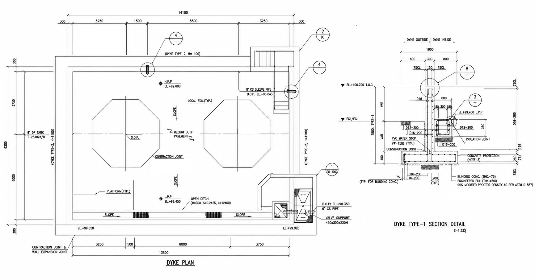
The above drawing represents a dyke wall layout plan and section detail used for industrial tank farms and process plants. It includes:
- Dyke wall layout plan
- Tank foundation arrangement
- Open drain system
- Valve pit arrangement
- Pipe sleeve details
- Expansion joints
- Construction joints
- Dyke wall sectional detail
- Reinforcement and waterproofing provisions
This article explains the layout, structural components, construction method, and engineering importance of dyke walls in detail.


What is a Dyke Wall?
A dyke wall is a containment barrier built around:
- Fuel storage tanks
- Diesel tanks
- Chemical tanks
- Transformer yards
- Oil handling areas
- Process equipment
It acts as a secondary safety containment system.
Main Functions of Dyke Wall
1. Spill Containment
Contains leaked oil or chemicals inside the protected area.
2. Fire Protection
Helps reduce spread of flammable liquid during emergencies.
3. Environmental Protection
Prevents contamination of soil and groundwater.
4. Safety Compliance
Required by industrial safety standards and petroleum regulations.
Puddle Flange Detail


Dyke Wall Layout Plan Explanation
The layout shown above consists of a rectangular RCC dyke enclosure with two storage tanks inside.
Main Components in the Layout
1. Dyke Wall Perimeter
The outer rectangular wall forms the containment boundary.
Typical specifications:
- RCC wall
- Height: 1100 mm
- Thickness: As per design
- Waterproof concrete construction
2. Storage Tanks
Two octagonal tank foundations are placed inside the dyke area.
The layout includes:
- Tank center lines
- Foundation positions
- Platform areas
- Pipe entry locations
3. Open Drain System
An open drain channel is provided inside the dyke.
Purpose:
- Remove rainwater
- Prevent water accumulation
- Direct spill liquids to collection pit
Typical drain slope:
- 0.2% to 0.5%
4. Pipe Sleeve Arrangement
Pipe sleeves are provided through dyke walls for process pipelines.
Features:
- CS sleeve pipe
- Waterproof sealing
- Isolation joint provision
5. Valve Support Area
Valve support structures are shown near the pipe outlet section.
Purpose:
- Support piping loads
- Reduce pipe stress
- Provide maintenance access
6. Staircase Access
A staircase is provided for safe operator access into the dyke enclosure.
Dyke Wall Section Detail Explanation
The sectional drawing explains the construction layers and reinforcement arrangement.
Components of Dyke Section
1. RCC Dyke Wall
The wall is constructed using reinforced cement concrete.
Typical specifications:
- Wall thickness: 200–300 mm
- Reinforcement: D12 or D16 bars
- Concrete grade: M25 or above
Functions:
- Resist hydrostatic pressure
- Prevent leakage
- Provide structural stability
2. Base Footing
The dyke wall is supported on an RCC footing.
Purpose:
- Distribute wall loads
- Prevent settlement
- Improve stability
3. Blinding Concrete
A 75 mm thick blinding concrete layer is provided below footing.
Benefits:
- Level surface for reinforcement
- Prevent soil contamination
- Improve construction quality
4. Engineered Fill
Compacted engineered fill is provided below the foundation.
Compaction requirement:
- 95% Modified Proctor Density
Purpose:
- Improve bearing capacity
- Reduce settlement
5. PVC Water Stop
PVC water stop is provided at construction joints.
Purpose:
- Prevent water seepage
- Improve waterproofing
6. Construction Joint
Construction joints are provided between concrete pours.
Importance:
- Controlled concrete casting
- Crack prevention
- Better structural behavior
7. Isolation Joint
Isolation joints separate pipes from concrete.
Benefits:
- Absorb vibration
- Allow thermal expansion
- Prevent cracking
Typical Dyke Wall Design Considerations
1. Dyke Capacity
Dyke volume should generally contain:
- 110% of largest tank capacity
OR - As per local industrial standards
2. Freeboard
Extra height provided above spill level.
Typical freeboard:
- 200 mm minimum
3. Waterproofing
Waterproofing is critical for:
- Oil resistance
- Chemical resistance
- Leakage prevention
Methods:
- Waterproof admixture
- Membrane coating
- Epoxy protection
4. Joint Treatment
Expansion joints and construction joints must be properly sealed using:
- PVC water stops
- Sealants
- Joint fillers
Construction Procedure of Dyke Wall
Step 1 – Site Preparation
- Excavation
- Soil compaction
- Layout marking
Step 2 – PCC / Blinding Concrete
- 75 mm PCC layer
- Surface leveling
Step 3 – Reinforcement Work
- Footing reinforcement
- Wall reinforcement
- Cover blocks
Step 4 – Formwork Installation
- Wall shuttering
- Alignment checking
- Joint provision
Step 5 – Concrete Pouring
- Footing concreting
- Wall concreting
- Vibration and compaction
Step 6 – Water Stop Installation
- PVC water stop fixing
- Joint treatment
Step 7 – Curing
- Minimum 7–14 days curing
- Crack prevention
Step 8 – Waterproofing
- Protective coating
- Joint sealing
Advantages of RCC Dyke Walls
High Structural Strength
Resists earth pressure and liquid pressure.
Long Service Life
Suitable for industrial environments.
Excellent Spill Protection
Protects environment and nearby equipment.
Low Maintenance
Requires minimal periodic maintenance.
Better Fire Safety
Contains hazardous liquid spread.
Applications of Dyke Walls
Dyke walls are commonly used in:
- Oil tank farms
- Petroleum plants
- Chemical industries
- Transformer yards
- LNG facilities
- Fuel stations
- Power plants
- Refineries
Important Engineering Notes
- Maintain proper slope inside dyke area.
- Provide oil-resistant sealants.
- Ensure adequate drain arrangement.
- Use corrosion-resistant reinforcement if required.
- Check local fire and pollution control regulations.
- Ensure proper expansion joint spacing.
Conclusion
The above dyke wall layout and section detail represent a complete industrial containment system designed for safety, spill control, and structural durability. Proper dyke wall design ensures environmental protection, operational safety, and long-term reliability in tank farm and industrial applications.
A well-designed RCC dyke wall with proper drainage, waterproofing, and joint detailing significantly improves plant safety and compliance with industrial standards.
- Splice Details for Angles
 Steel angle sections are one of the most commonly used… Read more: Splice Details for Angles
 - Mordern Floor Tile Design 50+
 Floor Tile Design Ideas – Elevate Your Spaces with Style… Read more: Mordern Floor Tile Design 50+
 - Room Paint Calculator | Quantity and Cost Estimator
 Looking to renovate your room? Our Room Paint, Primer &… Read more: Room Paint Calculator | Quantity and Cost Estimator
 - Manhole Cover Detail
 Manhole covers are one of the most important components in… Read more: Manhole Cover Detail
 - Commercial House Plan with 2 Shops | East Facing
 Looking for a modern commercial-cum-residential building plan that generates rental… Read more: Commercial House Plan with 2 Shops | East Facing
 - Circular Pipe Base Plate Design | AISC ASD Guide + PDF Download
 Introduction The base plate is one of the most important… Read more: Circular Pipe Base Plate Design | AISC ASD Guide + PDF Download
 - Side Cladding Runner Details for PEB Structures
 Introduction Side cladding runners are one of the most important… Read more: Side Cladding Runner Details for PEB Structures
 - Expansion Joints in Concrete Pavements
 Concrete pavements are designed to withstand heavy traffic loads, temperature… Read more: Expansion Joints in Concrete Pavements
 - Australian Wind Load Calculator as per AS/NZS 1170.2:2021
 Australian Wind Load Calculator | AS/NZS 1170.2:2021 Australian Wind Load… Read more: Australian Wind Load Calculator as per AS/NZS 1170.2:2021
 - Wind Load Calculator as per IS 875 Part 3:2015
 Industrial Shed Wind Load Calculator | IS 875 Part 3:2015… Read more: Wind Load Calculator as per IS 875 Part 3:2015
 - RCC Staircase Detail Drawing free pdf Download
 Reinforced Cement Concrete (RCC) staircases are one of the most… Read more: RCC Staircase Detail Drawing free pdf Download
 - Modern 35×40 House Design with Premium Front Elevation
 Building a dream home on a 35×40 plot is one… Read more: Modern 35×40 House Design with Premium Front Elevation
 - Pipe Rack GA Drawing Layout
 Image – Typical Pipe Rack GA Drawing Explanation The above… Read more: Pipe Rack GA Drawing Layout
 - House Plan 30×40 West Facing | 2BHK Luxury Floor Design |
 Designing a compact yet spacious home on a 30×40 plot… Read more: House Plan 30×40 West Facing | 2BHK Luxury Floor Design |
 - Bund Wall Detail Drawing for Tank Farm and Oil Storage Area
 Introduction A bund wall (also called a dyke wall or… Read more: Bund Wall Detail Drawing for Tank Farm and Oil Storage Area
 - Dyke Wall Layout and Detail | Oil Tank Containment Systems |
 Introduction A dyke wall (also called a bund wall or… Read more: Dyke Wall Layout and Detail | Oil Tank Containment Systems |
 - Apartment Plan 28×32 West Facing with Modern Elevation
 This project showcases a well-planned 30×40 west-facing apartment design featuring… Read more: Apartment Plan 28×32 West Facing with Modern Elevation
 - How to Assign LY and LZ in STAAD for Steel Structures (With and Without Bracing)
 🔹 What is LY and LZ? In STAAD.Pro: These define… Read more: How to Assign LY and LZ in STAAD for Steel Structures (With and Without Bracing)
 - HOUSE PLAN 35 X 41 | EAST FACING |
 Designing a perfect home requires a balance of functionality, aesthetics,… Read more: HOUSE PLAN 35 X 41 | EAST FACING |
 - EDG Building Power Cable Layout with MTO Guide
 Introduction An Emergency Diesel Generator (EDG) system is a critical… Read more: EDG Building Power Cable Layout with MTO Guide
 - Septic Tank Drawing and Details
 Septic tanks are widely used in residential buildings for on-site… Read more: Septic Tank Drawing and Details
 - Holding Tank Detail
 Introduction A holding tank, also known as a water sump… Read more: Holding Tank Detail
 - Rain Water Harvesting System pdf Book Download
 TABLE OF CONTENTS 1.0 INTRODUCTION 3 2.0 CHAPTER 1 4… Read more: Rain Water Harvesting System pdf Book Download
 - Galvanized Gate | Design Details and Specifications Guide |
 Introduction Industrial galvanized gates are designed for heavy-duty usage, high… Read more: Galvanized Gate | Design Details and Specifications Guide |
 - Soak Pit Details | Seepage Pit |
 Introduction A soak pit or seepage pit (also called a… Read more: Soak Pit Details | Seepage Pit |