
DESIGN OF CORBEL
A corbel is a short cantilever used to support structural loads like beams or girders projecting from a column or wall. It is commonly found in reinforced concrete and steel structures. The design of a corbel should ensure that it is capable of safely transferring vertical loads from beams to columns or walls.
Key Design Considerations for a Corbel:
- Load Transfer Mechanism:
- Corbels are designed to transfer vertical loads, shear forces, and moments from beams or girders to columns or walls. The main forces acting on a corbel are shear and bearing stresses.
- Dimensions:
- Depth (h): The depth of the corbel should be sufficient to resist shear and to avoid failure due to crushing. Typically, the corbel’s depth is about 0.5 to 0.7 times the depth of the supported beam.
- Projection Length (L): The projection should not exceed 1/2 of the effective depth (h) of the corbel to maintain stability and limit bending moments.
- Width (b): The width of the corbel is generally equal to the width of the supporting column or wall.
- Reinforcement Design:
- Main Reinforcement: Reinforcing bars are provided near the top of the corbel to resist the tensile stresses. These bars should be anchored adequately into the column or wall.
- Shear Reinforcement: Shear links or stirrups are provided to resist vertical shear forces. Horizontal stirrups are also placed near the base of the corbel to handle diagonal tensile forces.
- Secondary Reinforcement: This includes anti-burst reinforcement, typically placed around the corbel to prevent bursting failure under concentrated loads.
- Bearing Plate (if needed):
- A steel bearing plate may be used at the top of the corbel to distribute the load uniformly and prevent local crushing.
- Anchorage:
- Proper anchorage of the reinforcement bars into the column or wall is critical to prevent failure. Hooks or bends in the reinforcement are provided to ensure proper load transfer.
- Concrete Strength:
- High-strength concrete is typically used for corbels to resist high compressive stresses. A minimum grade of M25 or M30 concrete is common in such structures.
Design Procedure for a Corbel:
- Determine Applied Loads:
- Vertical load PPP, and any horizontal load (if applicable).
- Shear Stress Calculation:
- The shear force is given by V=PV = PV=P. The design should ensure the shear capacity of the concrete and reinforcement is adequate.
- Check Bearing Stress:
- Ensure the bearing area between the corbel and the beam is large enough to prevent crushing of concrete.
- Tension Reinforcement Design:
- Calculate the required area of steel based on the bending moment and tensile stresses. Reinforcing bars are placed in the top face of the corbel to resist the tensile force.
- Shear Reinforcement Design:
- Determine the necessary shear reinforcement to resist vertical and horizontal forces.
- Check for Failure Modes:
- Ensure the design addresses potential failure modes, including shear failure, crushing of concrete, and bursting failure.

Corbel Detailing:
- Main Tension Reinforcement:
- These bars are placed near the top surface of the corbel and anchored into the column. They should extend beyond the theoretical cutoff point to prevent premature failure.
- Shear Links:
- Vertical or horizontal stirrups are provided to resist shear and diagonal tensile forces. These links are placed along the height of the corbel.
- Anti-Bursting Reinforcement:
- Additional reinforcement is provided near the base of the corbel to handle tensile stresses caused by the concentrated load acting on a small area.
- Anchorage of Reinforcement:
- Reinforcement should be adequately anchored into the column, ensuring sufficient development length.
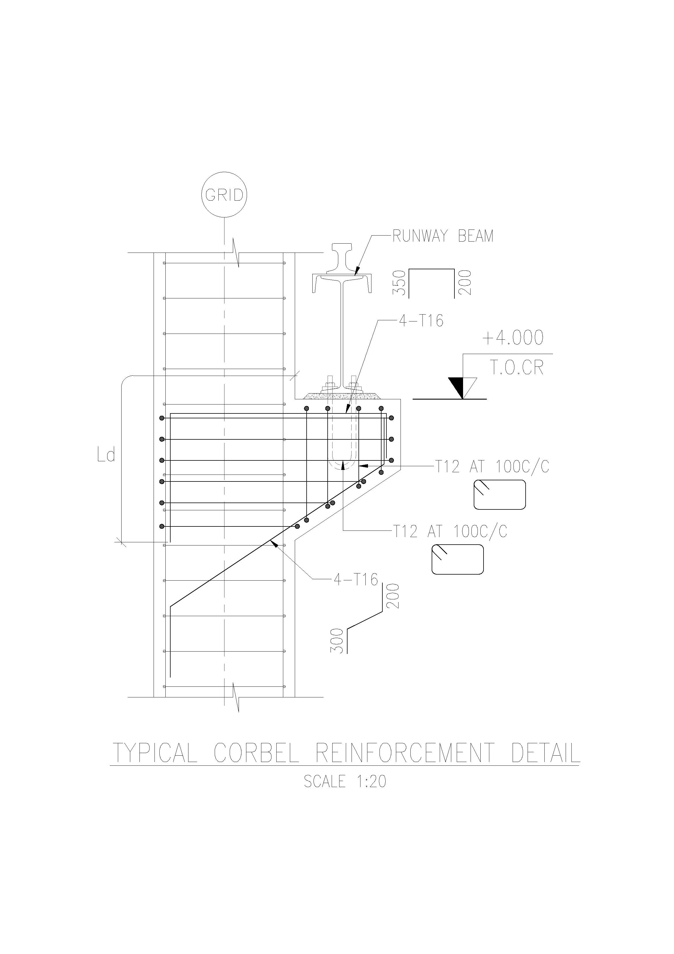
Typical Corbel Reinforcement Layout:
- Main Reinforcement: Top layer with bars extending into the column.
- Shear Stirrups: Vertical and horizontal shear links along the height of the corbel.
- Additional Ties: Diagonal or horizontal reinforcement near the corbel’s bottom to resist bursting.

Corbel Design Example:
For a corbel supporting a vertical load PPP of 100 kN with a projection of 300 mm and a depth of 500 mm:
- Determine the bending moment: M=P×LM = P \times LM=P×L, where LLL is the projection length.
- Calculate required reinforcement based on the moment and the concrete’s tensile strength.
- Check shear stress using appropriate shear reinforcement.
- Ensure anchorage and bursting reinforcement are adequate for safe load transfer.
Corbel designs should adhere to the respective code provisions, such as IS 456:2000 for reinforced concrete design in India or ACI 318 in the U.S.
Data:
1 Wheel Load from the Crane = 10 T
2 Spacing of the Wheels = 3.15 m
3 Spacing of the Columns = 6 m
4 Width of Column = 450 mm
Consider the Load position shown below:

Taking Moments about B,
RA = 10 * (2.85 + 6) = 14.75 T
6
Take 15 T (considering Gantry Weight etc.)

Design Shear Force = 14.75 * 1.5 * 9.807 = 216.98 kN
Assuming an allowable stress in concrete as 1 Mpa the depth required = = 216.98 * 1000
1 * 450
= 483 mm
\ Overall depth required = 483 + 35 = 518 mm
Provide 600 mm over all depth
\ Effective Depth = 600 – 35 = 565 mm
Lever arm z = 0.85 * d = 0.85 * 565 = 480.25 mm
Moment at the Face of the Column = 216.98 * 0.35 = 75.943 kNm
As = M = 75.943 * 10^6
0.87 x z xfy 0.87 * 480.25 * 415
= 438 mm2
Ah = 0.5 As = 0.5 * 438 = 219 mm2
rv = As + Ah = 438 + 219 = 0.002584071
bd 450 * 565
Now, fc’ / fy = 0.8 * 25 / 415 = 0.049
\ 0.2 fc’ / fy = 0.2 * 0.049 = 0.0098
It is noted that 0.2 * fc’ / fy is < rv
Allowable Stress tv = 6.5 (1 – L / 2d) *(1 + 64rv)Ö fc’
= 281.5472836 psi
= 1.94 Mpa
Actual Shear Stress tv = 216.98 x 1000 = 0.854 Mpa 450 x 565
Allowable Stress tv > Actual Stress OK.
Note: The value of fc’ shall be in psi; In this case fc’ = 0.8 * 25 Mpa = 2899.4 psi
(Reference: Reinforce Concrete Structures by R. Park and T. Paulay, John Wiley and Sons)
Categories
- 3D HOUSE DESIGN (42)
- Auto Calculator – Civil & Structural Engineering Calculation Tools (11)
- Civil and Structural Design Calculations (85)
- Commercial Plans (9)
- East Facing House Plans (16)
- Engineering Concepts – Civil & Structural (259)
- Excel Spreadsheets (37)
- Free Downloads (54)
- House Plans (64)
- Industrial standards (111)
- North Facing House Plans (16)
- South Facing House Plans (16)
- West Facing House Plans (13)
Recent Posts
- Splice Details for Angles
- Mordern Floor Tile Design 50+
- Room Paint Calculator | Quantity and Cost Estimator
- Manhole Cover Detail
- Commercial House Plan with 2 Shops | East Facing
- Circular Pipe Base Plate Design | AISC ASD Guide + PDF Download
- Side Cladding Runner Details for PEB Structures
- Expansion Joints in Concrete Pavements
- Australian Wind Load Calculator as per AS/NZS 1170.2:2021
- Wind Load Calculator as per IS 875 Part 3:2015
- RCC Staircase Detail Drawing free pdf Download
- Modern 35×40 House Design with Premium Front Elevation
- Pipe Rack GA Drawing Layout
- House Plan 30×40 West Facing | 2BHK Luxury Floor Design |
- Bund Wall Detail Drawing for Tank Farm and Oil Storage Area
- Dyke Wall Layout and Detail | Oil Tank Containment Systems |
- Apartment Plan 28×32 West Facing with Modern Elevation
- How to Assign LY and LZ in STAAD for Steel Structures (With and Without Bracing)
- HOUSE PLAN 35 X 41 | EAST FACING |
- EDG Building Power Cable Layout with MTO Guide
- Septic Tank Drawing and Details
- Holding Tank Detail
- Rain Water Harvesting System pdf Book Download
- Galvanized Gate | Design Details and Specifications Guide |
- Soak Pit Details | Seepage Pit |
- HOUSE PLAN 25 X 48 | SOUTH FACING |
- Expansion, Contraction and Construction Joints in Concrete for Civil Works
- Modern 4BHK West Facing House Plan (60×50) with Pool & Luxury 3D Design
- Cable Rack Structural Steel Detail and Design
- RCC Shear Wall Details
- RCC Column with Splice and Coupler in Reinforcement Free Download
- Repair Principles for Corrosion Damaged Reinforced Concrete Structures
- Civil Engineering Guide to Concrete Repair and Strengthening
- Australian Code Load Combinations
- Modular Kitchen | Kitchen Cabinet Design Ideas with Cost |
- Bathroom Design Ideas for Modern Homes
- Manhole Types and Details
- Catch Basin Types and Details
- Eurocode Base Plate Calculator – EN 1993-1-8
- Base Plate Design Calculation AS 4100
- Base Plate Design Calculator CSA A23.3
- Base Plate Design Calculator ACI 318
- Base Plate Design as per IS 800 2007
- East Facing 38×56 House Plan – Ground & First Floor Design with 3BHK + Home Theatre
- Foundation Detail Drawings for Buildings With CAD Files
- Bar Bending Schedule | BBS Calculator For Beam Column and Slab
- Load Conversion & Stress Calculator | kN to kg, ton, N, MPa Online
- Water Tank Capacity Calculator – Feet & Meter Conversion (Litres & Gallons)
- Brick Wall Construction Calculator | Calculate Bricks & Cost Instantly |
- Unit Converter – Feet, Inches, cm, mm, Yard to Meter and Vice Versa