An RCC lift pit is the reinforced concrete structure constructed below the lowest lift landing level to provide the required space for the lift car, buffers, guide rails and other lift components. A properly detailed lift pit must consider structural loads, soil pressure, groundwater, waterproofing, reinforcement continuity and the requirements of the selected lift manufacturer.
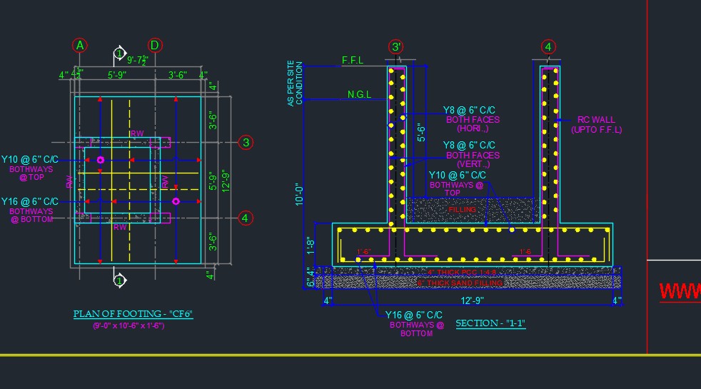
This article explains the important components normally shown in an RCC lift pit structural drawing, including the pit slab, RCC walls, reinforcement, waterproofing, construction joints, sump and buffer support areas.
Important: Lift pit dimensions, pit depth, buffer loads and guide-rail reactions vary between lift manufacturers. Final structural dimensions and reinforcement should therefore be designed using the approved lift manufacturer’s GA drawing and reaction/load schedule.
1. What Is an RCC Lift Pit?
The lift pit is the portion of the lift shaft located below the lowest finished floor level.
A typical RCC lift pit consists of:
RCC pit base slab
RCC pit walls
Reinforcement in both directions
Starter bars and wall-slab connection
Waterproofing system
PCC below the RCC slab
Water-stop at construction joints
Lift buffer support/pedestal
Guide-rail support locations
Drainage/sump arrangement where required
Access ladder and other lift-related provisions
The pit essentially acts as a reinforced concrete box below ground level. Because it is commonly surrounded by soil, the pit walls may be subjected to lateral earth pressure and, depending on site conditions, hydrostatic water pressure.
2. Typical RCC Lift Pit Arrangement
A typical structural drawing may include the following arrangement:
The exact pit depth must come from the selected lift system. There is no universal pit depth because hydraulic, traction, screw and other lift systems can have substantially different requirements.
4. RCC Pit Base Slab
The pit base slab forms the bottom of the lift pit and transfers the applicable loads into the supporting soil/foundation system.
The structural engineer should consider:
Self-weight of the slab
Soil bearing condition
Groundwater pressure/uplift
Lift buffer reactions
Equipment loads
Local concentrated loads
Foundation interaction
Punching/shear where applicable
Crack control and durability
The slab reinforcement is normally detailed in both directions, with top and bottom reinforcement as required by structural analysis.
A typical drawing notation may look like:
BASE SLAB
T12 @ 150 c/c BOTH WAYS
TOP & BOTTOM
However, this is only an illustrative detailing example. Reinforcement must not be adopted directly without structural design.
5. RCC Lift Pit Walls
The pit walls retain the surrounding soil and form the sides of the waterproof concrete box.
The wall design should consider:
Earth pressure
The buried pit wall can be subjected to lateral soil pressure.
Hydrostatic pressure
Where groundwater is present, water pressure can act on the outside of the pit wall.
Lift equipment reactions
Guide rails, brackets and other lift components may introduce local forces into the shaft structure. The lift manufacturer should provide the relevant reactions and fixing requirements.
Reinforcement
Pit walls are generally reinforced vertically and horizontally.
Again, these values are examples for explaining drawing notation and are not standard reinforcement values for every lift pit.
6. Wall-to-Slab Connection
One of the most important areas in the lift pit detail is the connection between the RCC wall and base slab.
The drawing should clearly show:
Wall starter bars
Development/lap length
Corner reinforcement
Construction joint
Water-stop
Concrete cover
Reinforcement continuity
The slab-wall joint is also a critical waterproofing location because construction joints can become paths for groundwater infiltration. Water-stops are commonly used where specified for underground RCC construction.
7. Lift Pit Waterproofing
Waterproofing is one of the most important requirements for an underground lift pit.
A lift pit can be exposed to:
Groundwater
Rainwater
Rising water table
Hydrostatic pressure
Leakage through construction joints
Cracks in concrete
Water infiltration can cause reinforcement corrosion and damage lift components.
The water-stop should be properly fixed to the reinforcement before concreting so that it remains in the specified position.
9. Lift Pit Sump
Depending on the project and lift manufacturer’s requirements, a small sump/drainage arrangement may be provided inside the pit.
The sump can help collect water for controlled removal.
The drawing should identify:
Sump dimensions
Sump depth
Reinforcement
Waterproofing
Drain connection, if provided
Pump arrangement, if required
The drainage arrangement should be coordinated with the architect, MEP engineer and lift supplier.
10. Buffer Support
Lift buffers are installed at the bottom of the lift pit.
The buffer location and reactions must be obtained from the lift manufacturer.
The pit slab or a local buffer support arrangement may need to resist concentrated impact/reaction forces. Therefore, the structural designer should not design the pit slab only for its self-weight and ordinary floor loading.
The drawing should clearly identify:
BUFFER SUPPORT / BUFFER LOCATION
       LIFT CAR
          │
          ▼
       ┌─────┐
       │BUFFER│
       └──┬──┘
          │
     BUFFER SUPPORT
══════════════════════
       RCC PIT SLAB
══════════════════════
11. Lift Guide-Rail Supports
Guide rails require suitable structural support at the locations specified by the lift supplier.
The RCC shaft/pit wall may require:
Embedded plates
Anchor channels
Inserts
Anchor bolts
Local reinforcement
Brackets
The exact arrangement should be coordinated with the lift manufacturer’s installation drawings before casting the RCC shaft.
12. Concrete Cover
The reinforcement cover must be selected based on the applicable structural code, exposure condition and project specification.
Because the lift pit is below ground and can be exposed to moisture, durability requirements are particularly important.
The structural drawing should clearly specify the required nominal cover rather than leaving it to site interpretation.
13. Typical Lift Pit Reinforcement Drawing Notes
A professional RCC drawing can include notes such as:
GENERAL NOTES
All dimensions are in mm unless otherwise noted.
All levels are in metres.
RCC grade shall be as specified in the structural design.
Reinforcement steel shall comply with the applicable project specification.
Reinforcement shall be provided as detailed in the structural drawings.
Lap lengths shall comply with the applicable structural code.
Reinforcement shall be properly supported with chairs/spacers.
Concrete cover shall be maintained as specified.
Provide water-stop at specified construction joints.
All lift openings and embedded items shall be coordinated with the lift supplier.
Do not modify structural reinforcement without approval from the structural engineer.
Final pit dimensions shall be checked against the approved lift manufacturer’s GA drawing.
14. Important Dimensions to Show in the Drawing
The lift pit drawing should ideally show:
Item
Drawing Requirement
Lift pit length
Dimension
Lift pit width
Dimension
Pit depth
Level/dimension
Wall thickness
Dimension
Base slab thickness
Dimension
PCC thickness
Dimension
Reinforcement
Bar size & spacing
Concrete cover
Dimension
Buffer location
Dimension
Sump
Dimension
Waterproofing
Detail
Water-stop
Detail
Construction joint
Detail
Guide rail support
Location
Lift shaft opening
Dimension
15. Construction Sequence
A typical construction sequence is:
Step 1 – Excavation
Excavate to the required formation level while maintaining safe excavation conditions.
Step 2 – Soil Preparation
Compact and prepare the formation as specified by the geotechnical/structural design.
Step 3 – PCC
Provide PCC/blinding concrete as specified.
Step 4 – Waterproofing
Install the specified waterproofing system where applicable.
Step 5 – Base Slab Reinforcement
Fix bottom and top reinforcement as per structural drawings.
Step 6 – Base Slab Concreting
Cast the RCC base slab with proper vibration and curing.
Step 7 – Pit Wall Reinforcement
Fix vertical and horizontal reinforcement and connect the wall reinforcement with the base slab reinforcement.
Step 8 – Water-Stop
Install water-stop at the specified construction joint.
Step 9 – Wall Formwork
Check dimensions, reinforcement cover, embedded items and lift interfaces.
Step 10 – RCC Wall Casting
Cast the pit walls and ensure proper compaction.
Step 11 – Waterproofing & Protection
Complete the specified external waterproofing/protection system.
Step 12 – Lift Installation
After the structural and finishing works are completed, install the lift equipment according to the manufacturer’s installation requirements.
16. Common Mistakes in RCC Lift Pit Construction
Some common problems include:
1. Fixing the pit depth before selecting the lift
This can create serious coordination problems.
2. Ignoring groundwater
A pit below ground level should be assessed for groundwater and hydrostatic pressure.
3. No water-stop
Construction joints without suitable water-control detailing can become leakage points.
4. Incorrect reinforcement cover
Insufficient cover can reduce durability and increase corrosion risk.
5. Missing buffer reactions
Buffer reactions can produce concentrated forces that need to be considered in structural design.
6. Missing guide-rail support
Lift rail supports should be coordinated before casting the shaft.
7. Changing reinforcement at site
Structural reinforcement should not be altered without approval.
8. Poor slab-wall joint detailing
The base slab/wall junction needs both structural and waterproofing attention.
17. Structural Design Considerations
The RCC lift pit should be designed considering the actual project conditions, including:
Soil bearing capacity
Soil unit weight
Earth pressure
Groundwater level
Hydrostatic pressure
Uplift
Pit dimensions
Concrete grade
Reinforcement grade
Buffer reactions
Guide-rail reactions
Lift equipment loads
Crack control
Durability
Construction joints
Waterproofing requirements
The structural engineer should obtain the approved lift manufacturer’s GA drawing and reaction schedule before finalizing the RCC pit design. This is particularly important because pit dimensions and equipment loads vary significantly between lift systems.
For a professional structural drawing, I recommend preparing one sheet containing:
SHEET – RCC LIFT PIT DETAIL
Drawing 1
Lift Pit Plan
Shows:
Overall dimensions
Wall thickness
Pit opening
Buffer locations
Sump
Reinforcement
Guide-rail locations
Drawing 2
Lift Pit Section A-A
Shows:
Ground level
Lowest floor level
Pit depth
RCC wall
Base slab
PCC
Waterproofing
Water-stop
Reinforcement
Buffer support
Drawing 3
Wall Reinforcement Detail
Shows:
Vertical bars
Horizontal bars
Lap/development
Corner reinforcement
Cover
Drawing 4
Slab Reinforcement Detail
Shows:
Bottom reinforcement
Top reinforcement
Extra reinforcement
Buffer support reinforcement
Drawing 5
Waterproofing Detail
Shows:
Waterproofing layer
RCC
Construction joint
Water-stop
Protection layer
Conclusion
An RCC lift pit is not simply a deeper portion of the lift shaft. It is a structural and waterproof underground RCC box that must safely accommodate the lift equipment and transfer the applicable loads into the supporting structure.
The most important items in the lift pit drawing are the pit dimensions, RCC wall and slab, reinforcement, buffer support, guide-rail supports, waterproofing, construction joints and water-stop details.
The final design should always be coordinated with the approved lift manufacturer’s GA drawing and reaction schedule. This prevents problems such as incorrect pit depth, insufficient clearance, misplaced buffer supports and conflicts with lift equipment.
Downloadable Drawing / Calculator Idea
For a civil and structural engineering website, this topic can be expanded into a useful resource containing:


 An RCC lift pit is the reinforced concrete structure constructed… Read more: RCC Lift Pit Detail – Reinforcement Drawing, Section & Waterproofing Guide
 Introduction Beam-to-column shear connections are among the most frequently used… Read more: Beam to Column Shear Connection
 Pile caps are one of the most important components in… Read more: Pile Cap Detail Drawing Free Download
 Steel angle sections are one of the most commonly used… Read more: Splice Details for Angles
 Looking to renovate your room? Our Room Paint, Primer &… Read more: Room Paint Calculator | Quantity and Cost Estimator
 Manhole covers are one of the most important components in… Read more: Manhole Cover Detail
 Introduction Side cladding runners are one of the most important… Read more: Side Cladding Runner Details for PEB Structures
 Concrete pavements are designed to withstand heavy traffic loads, temperature… Read more: Expansion Joints in Concrete Pavements
 Reinforced Cement Concrete (RCC) staircases are one of the most… Read more: RCC Staircase Detail Drawing free pdf Download
 Image – Typical Pipe Rack GA Drawing Explanation The above… Read more: Pipe Rack GA Drawing Layout
 Introduction A bund wall (also called a dyke wall or… Read more: Bund Wall Detail Drawing for Tank Farm and Oil Storage Area
 Introduction A dyke wall (also called a bund wall or… Read more: Dyke Wall Layout and Detail | Oil Tank Containment Systems |
 🔹 What is LY and LZ? In STAAD.Pro: These define… Read more: How to Assign LY and LZ in STAAD for Steel Structures (With and Without Bracing)
 Introduction An Emergency Diesel Generator (EDG) system is a critical… Read more: EDG Building Power Cable Layout with MTO Guide
 Septic tanks are widely used in residential buildings for on-site… Read more: Septic Tank Drawing and Details
 Introduction A holding tank, also known as a water sump… Read more: Holding Tank Detail
 TABLE OF CONTENTS 1.0 INTRODUCTION 3 2.0 CHAPTER 1 4… Read more: Rain Water Harvesting System pdf Book Download
 Introduction Industrial galvanized gates are designed for heavy-duty usage, high… Read more: Galvanized Gate | Design Details and Specifications Guide |
 Introduction A soak pit or seepage pit (also called a… Read more: Soak Pit Details | Seepage Pit |
 1. Introduction Concrete is one of the most widely used… Read more: Expansion, Contraction and Construction Joints in Concrete for Civil Works
 Introduction Cable racks (also called cable trays or cable support… Read more: Cable Rack Structural Steel Detail and Design
 Introduction Reinforced Cement Concrete (RCC) shear walls are one of… Read more: RCC Shear Wall Details
 Introduction Reinforced Cement Concrete (RCC) columns are one of the… Read more: RCC Column with Splice and Coupler in Reinforcement Free Download
 Manholes are essential underground structures used in sewer systems, stormwater… Read more: Manhole Types and Details
 Catch basins are essential components of stormwater management systems. They… Read more: Catch Basin Types and Details
Leave a Reply