
How to calculate the development length for different grades of concrete as per IS 456?
Development Length Formula
As per IS Code 456:2000, (Clause 26.2.1) Development length can be calculated using the below formula
Ld = Фσs/4τbd
Where,
Ф = diameter of the reinforcement bar
σs = Stress developed in a bar at section considered at load design
τbd = Design bond stress
Note- The formula can be used for both the Limit state and the Working stress method. It only differs in design bond stress value.
REASONS FOR PROVIDING DEVELOPMENT LENGTH:
There are the following reasons for providing this length as given below;
- Between the bar surface and the concrete to develop a safe bond.
- Due to slippage of bar occurring during the ultimate load conditions no failure occurs.
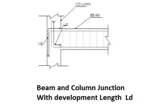
- For transferring the stresses developed in any section to the adjacent sections the extra length of the bar provided as development length is responsible for example at column beam junction the additional length of bars provided from beam to column.
Development Length Calculation

CHECK | |||||||||||
Max | 31.75 | KN | Design | ||||||||
Grade | 25 | Greade | 15 | 20 | 25 | 30 | 35 | 40 | |||
Grade | 415 | Tbd | 1.0 | 1.2 | 1.4 | 1.5 | 1.7 | 1.9 | |||
Adopt | 250 | mm | |||||||||
Width | 1000 | mm | |||||||||
Dia of | 10 | mm | |||||||||
Area of | 512 | Sqmm | |||||||||
Area of | 78.57 | Sqmm | |||||||||
Spacing | 150 | mm | |||||||||
Assumed | 200 | mm | |||||||||
INPUT | Bond | 1.4 | N/Sqmm | ||||||||
Development | |||||||||||
Ld= | |||||||||||
Ld in | 644 | mm | |||||||||
Development | |||||||||||
Ld= 1.3 | |||||||||||
INPUT | Assumed | 140 | mm | ||||||||
Moment | 10 | mm dia | 300 | Nos | |||||||
M1 = | 4,46,47,000 | Nmm | |||||||||
V = | 31750 | N | Development Length for Single Bars | ||||||||
Ld in | 1968 | mm | fy N/Sqmm | Tension Bars | Compression Bars | ||||||
Factor | 56 |
| M15 | M20 | M15 | M20 | |||||
Develop | 560 | mm | 250 | 55Ø | 46Ø | 44Ø | 37Ø | ||||
415 | 56Ø | 47Ø | 45Ø | 38Ø | |||||||
Max | 1968 | mm | 500 | 69Ø | 58Ø | 54Ø | 46Ø | ||||
Max Bar | 49 | mm | |||||||||
Check for Development Length | OK | If NOT | |||||||||
Product categories
Recent Posts
- Modular Kitchen | Kitchen Cabinet Design Ideas with Cost |
- Bathroom Design Ideas for Modern Homes
- Manhole Types and Details
- Catch Basin Types and Details
- Eurocode Base Plate Calculator – EN 1993-1-8
- Base Plate Design Calculation AS 4100
- Base Plate Design Calculator CSA A23.3
- Base Plate Design Calculator ACI 318
- Base Plate Design as per IS 800 2007
- East Facing 38×56 House Plan – Ground & First Floor Design with 3BHK + Home Theatre
- Foundation Detail Drawings for Buildings With CAD Files
- Bar Bending Schedule | BBS Calculator For Beam Column and Slab
- Room Paint Calculator | Paint, Primer & Putty Quantity & Cost Estimator
- Load Conversion & Stress Calculator | kN to kg, ton, N, MPa Online
- Water Tank Capacity Calculator – Feet & Meter Conversion (Litres & Gallons)
- Brick Wall Construction Calculator | Calculate Bricks & Cost Instantly |
- Unit Converter – Feet, Inches, cm, mm, Yard to Meter and Vice Versa
- Lifting Analysis of Skid Using Spreader Beam 4-Point
- Base Plate Design as per IS Code | IS 800:2007 Steel Column Base |
- Laser Cut Railing Price in India 2025 | MS & SS CNC Balcony Designs
- MS Balcony Railing Price in India 2026 | Mild Steel Railing Works |
- Stainless Steel with Glass Handrail Price 2026
- Modern Duplex House West Facing 36 x 48
- Pooja Room Door Design
- Modern House 3D Design – Visualizing Your Dream Home
- Balcony Railing Designs for Modern Homes
- Civil Engineering Interview Questions and Important Practical Foundation
- Wind Load Calculation IS 875 Part 3 2015
- Front Elevation Design for Modern Homes
- Road Turning Radius as per IS/IRC Codes and International Standards AASHTO BS/DMRB
- Foundation Design ACI 318 pdf & Excel Download
- Steel Staircase Design
- Front Elevation 20×60 House
- Steel Shed with Mezzanine Floor
- Structural Masonry Designers Manual
- Water Supply Piping Plan and Plumbing Schematic Diagram
- Sump Pit Drawing
- Design of Steel Silo
- Design of Beam to Beam End Plate Connection
- DESIGN OF FLAT SLAB pdf Free Download
- Design of Thrust Block
- Cage Ladder Detail Standard Drawing pdf Free Download
- DESIGN OF BARREL FOR BOX CULVERT pdf Free Download
- Design of Retaining Wall Calculation pdf Free Download
- Analysis and Design of Drain Sump Pit
- Design of High Rise Buildings as per Eurocode
- Design of Steel Shelter as per IS 800
- Octagonal Pedestal Design
- Ring Wall Foundation Design
- Decking Sheet with Concrete – Design Details & Specifications
- Hydrodynamic Load on Tanks | Convective and Impulsive |
- PILE STIFFNESS CALCULATION
- HOUSE PLAN 30 X 60 | SOUTH FACING |
- Concrete Beam Design ACI 318
- Floor Slab Design One Way as per ACI 318
- Floor Slab Design Two way as per ACI 318
- Ceiling Lights and Fan Layout Details
- Floor Tile Design Ideas
- Modern Boundary walls
- Lintel Slab Layout Details
- PILE CAP Detail Drawing
- Eurocode Load Combinations EN 1990 2002
- Expansion Joint Detail and Specification
- Storm Water Drain Detail Drawing
- Thrust Blocks and Restraints Details
- HOUSE PLAN 40 X 50 | SOUTH FACING |
- Octagonal Foundation Reinforcement Details
- Loads and Load Combinations as per AS/NZS 1170.0 2002
- Design of Pump Foundation Dynamic and Static Analysis
- HOUSE PLAN 60 X 40 | WEST FACING |
- Latest Staircase Handrail Design Ideas 40+
- HOUSE PLAN 50 X 50 | SOUTH FACING |
- Electrical Layout For Residential Building
- HOUSE PLAN 29 X 56 | SOUTH FACING |
- Rain Water Gutter and Down Take Systems
- Stormwater Drainage Calculation
- Structural Engineering Design Criteria – American Codes and Standards
- Anchor Bolts Length as per ACI 318-14
- Insert Plate Details & Drawing – Embedded in Concrete Structures
- JOURNAL PAPER GUIDELINES FOR ACSE
- Anchor Bolt Details and Drawing – Embedded in Concrete
- Staircase Layout and Details
- Guard House Layout and Details
- Pump Shed Structural Steel Drawing
- Wind Load Calculations ASCE 7-16 Pdf Free Download
- Column Buckling
- Moody Chart | Moment Reactions for Rectangular Plates |
- Test Pile Drawing Calculation & Guidelines
- Commercial Shop Plan
- Shop Floor Plan
- HOUSE PLAN WITH SHOP 40 x 60 | SOUTH FACING |
- Wind Load Calculation as per Australian Code (AS/NZS 1170.2:2021)
- HOUSE PLAN 30 X 45 | EAST FACING | INTERIOR HOUSE DESIGN |
- HOUSE PLAN 60 x 40 | EAST FACING | APARTMENT TYPE |
- Standard Road Details
- DG Building Architectural Plan & Finishing Schedule
- AMAZING TV UNIT IDEAS 90+ MODELS
- HOUSE PLAN 60 x 50 | EAST FACING |
- Technical Details for Wash Basin Section and Elevation
- Tender Technical Specification for Plumbing and Sanitary works
- HOUSE PLAN 25 x 50 | SOUTH FACING |
- HOUSE PLAN 60 x 45 | SOUTH FACING |
- Fencing Gate Details and Requirements
- Fencing Layout and Details For Transformer Area
- Fencing with Angle Post and Pipe Post Details & Arrangements
- Civil Engineering Formula Book | Pocket Guide pdf Free download |
- HOUSE PLAN 35 x 60 | WEST FACING |
- Transformer Foundation with Soak Pit Layout and Details
- Grating Standard Details and Specifications
- Chequered Plate Standard Details
- Handrail Details for Steel Structural Floors
- Cable Pull Pit Requirements and Details
- Laboratory Building Plan and Architecture Details
- Structural Bolt Details Types Grades and Applications
- HOUSE PLAN 40 x 60 | NORTH FACING |
- Finishing Schedule Drawing for Doors, Windows, and Rolling Shutters
- Workshop Building Architectural Layout
- Calculation of Foundation Bearing Capacity as per IS 6403 – 1981
- Terzaghi’s Bearing Capacity Calculation For Foundations
- DESIGN AND CONSTRUCTION METHOD OF MULTISTORY CONCRETE BUILDINGS
- HOUSE PLAN 60 x 60 | SOUTH FACING |
- Civil Structural Engineering Interview Questions pdf Free Download
- Civil Structural Engineering Interview Questions
- HOUSE PLAN 60 x 30 | EAST FACING |
- HOUSE PLAN 28 x 31 | WEST FACING |
- SHEAR FORCE AND BENDING MOMENT DIAGRAMS WITH FORMULA
- HOUSE PLAN 43 x 66 | SOUTH FACING |
- Canadian Code Seismic Calculation Example
- Weathering Course in RCC Roof
- Rolling Shutter Fixing Detail with RCC Beam
- HOUSE PLAN 35 x 50 | SOUTH FACING |
- APARTMENT PLAN 53 x 62 | EAST & WEST Facing |
- Duct Bank Details and Pipe Sleeves Details
- Handrail Details | Construction Methods and Types of Handrail |
- Details of Ramp
- Design Calculation of Steel Shelter – AISC 360
- Cage Ladder Specification and Detail Drawing
- Staircase Ideas 40+
- Vertical Vessel Foundation Design
- Effective Length for RCC Columns
- DESIGN OF SLABS AS PER IS456
- Design of Staircase Waist Slab
- Monorail Beam Design
- HOUSE PLAN 35 x 50 | SOUTH FACING |
- Concrete Beam Design as per Canadian Code (CSA A23.3-19)
- Wind Load Calculation as per Canadian Code | NBCC 2020 |
- Fencing Detail Drawing
- HOUSE PLAN 40 x 60 | NORTH FACING |
- HOUSE PLAN 60 x 30 | SOUTH FACING |
- RCC Fencing Post Details
- HOUSE PLAN 30 x 40 | NORTH FACING |
- HOUSE PLAN 45 x 45 | WEST FACING |
- HOUSE PLAN 40 x 40 | WEST FACING |
- HOUSE PLAN 30 x 50 | SOUTH FACING |
- Modern House Front Elevation Design
- Transformer Foundation Design
- Gypsum Board False Ceiling Installation
- Box Culvert Design
- Design of Anchor Reinforcement in Concrete Pedestals
- Wind Load Calculation for Pipe Rack
- Apartment House Plan | West Facing 60 x 60 |
- kitchen marble design 30+
- Wind Load Calculation as Per Indian Code
- DESIGN BASIS FOR CIVIL AND STRUCTURAL
- General Specification for Civil and Structural Works
- Green Building
- Fireproofing Details
- Response Spectrum Analysis in STAAD pro
- SHELTER WITH 25T CRANE DRAWING | PEB SHED |
- HOUSE PLAN 20 x 60 | WEST FACING |
- MONORAIL DETAILS
- WEST FACING HOUSE PLAN 50 x 40 | DUPLEX TYPE |
- Side Face Reinforcement as per ACI & IS code
- HOUSE PLANS
- HOUSE PLAN 35 x 50 | EAST FACING |
- HOUSE PLAN 25 x 60 | NORTH FACING |
- HOUSE PLAN 35 x 50 | NORTH FACING |
- Design of Cold-Formed Steel Structures as Per IS 801
- HOUSE PLAN 30 x 40 | EAST FACING |
- HOUSE PLAN 30 x 40| NORTH FACING |
- HOUSE PLAN 20 x 40 | NORTH FACING |
- Lifting Padeye Design
- Corbel Design and Details
- DYNAMIC ANALYSIS USING RESPONSE SPECTRUM ANALYSIS
- Building Load Calculation
- Deep Excavations
- Bathroom Tiles Designs Ideas 50+
- Wooden Main Door Ideas 40+
- Gate Design Ideas 60+
- Structural Design of working pile
- Design of Gantry Girder
- Modern Kitchen Interior Idea Photos 26+
- BEHAVIOUR OF STEEL CHIMNEY UNDER DYNAMIC LOADINGS
- Church Design Drawing
- Seismic Load Calculation as per ASCE 7-16
- 33×66 North Facing Ground Floor Plan with Vastu
- DESIGN OF WIND PRESSURE AS PER EN 1991-1-4
- Best 3D House Elevation Design G+1
- House Plan with Photos | Architect Detail Drawing |
- Trench Details
- PRECAST COVER SLAB DETAILS
- Grade Slab Details
- Resort Cottage Plan
- CONCRETE BATCHING PLANT ARRANGEMENT
- LOAD COMBINATIONS NBCC 2023
- STEEL SHED DRAWING
- Plumbing Drawing
- Pre Engineered Building Design Specification IS Code
- SMALL HOUSE PLAN 28 x 40 | NORTH FACING |
- DESIGN OF PIPERACK STRUCTURE
- BATHROOM FIXTURES AND FITTINGS – European Closet, Urinal & Wash Basin
- DUPLEX HOUSE PLAN 30 x 30 | EAST FACING |
- HOUSE PLAN 29 x 44 | EAST FACING | DUPLEX HOUSE
- Design of Pipe Support Foundation Calculation
- FLAT SLAB DESIGN AND DETAILING
- DIRECT ANALYSIS METHOD AISC 360-05 AND ITS IMPLEMENTATION IN STAAD
- PILE FOUNDATION | TYPE OF PILES | TEST METHODS AND SITE EXECUTION |
- HOUSE PLAN 38 x 58 | BEST EAST FACING | HOME THEATER
- Front Elevation Design 30+
- Design of Concrete Anchor Blocks
- HOUSE PLAN WITH OFFICE AT GROUND FLOOR 27 x 88 | NORTH FACING |
- Design of Shear Key in Base Plate as per IS Code
- HOUSE PLAN 45 x 40 | BEST NORTH FACING BUILDING PLAN |
- BANQUET HALL PLAN 40 x 60 | NORTH FACING |
- MARRIAGE HALL PLAN 33 x 77 | SOUTH FACING |
- COMMERCIAL PLAN 48 x 40 | NORTH FACING |
- APARTMENT TYPE HOUSE PLAN 30 x 80 | EAST FACING | 3BHK
- APARTMENT PLAN 40×50 | EAST FACING | 3BHK |
- Concrete Mix Design Calculations
- PEB Shed Drawing
- HOUSE PLAN 40 x 46 | NORTH FACING |
- DEVELOPMENT LENGTH OF REBAR