
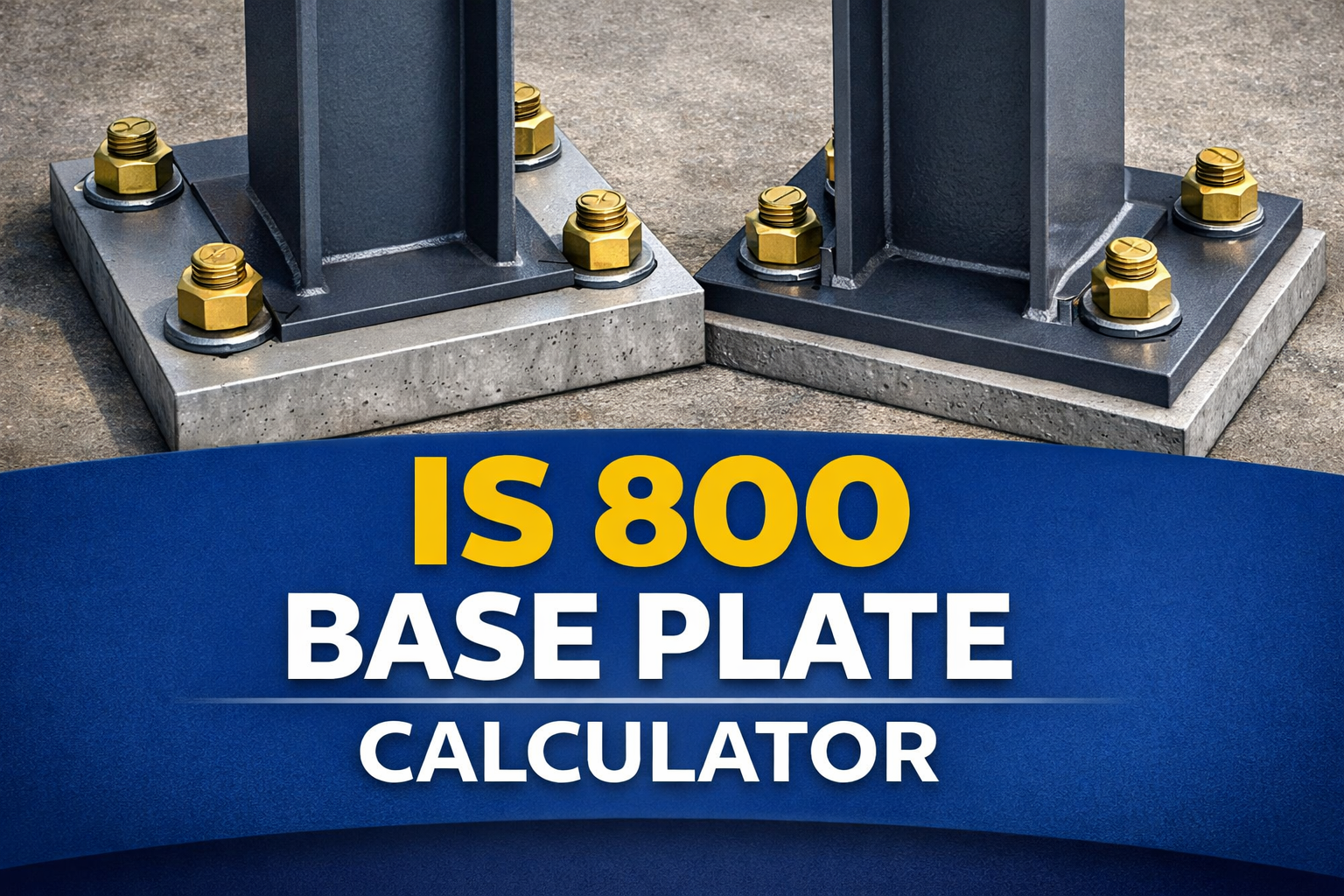
Introduction (Anchor Bolts Outside & Inside Column Flange)
Base plates are critical steel connection elements used to safely transfer axial load, bending moment, and shear force from a steel column to the concrete foundation.
As per IS 800:2007 – General Construction in Steel, base plate design ensures adequate bearing, bending resistance, and anchorage safety.
This article explains the step-by-step design of a base plate with anchor bolts located outside the column flange, which is commonly adopted for heavily loaded columns and moment-resisting frames.
Base Plate Design Calculator (IS 800:2007)
Preliminary design of steel column base plates with anchor bolts inside or outside column flange.
Input Parameters
Detailed Design Calculations (Auto-Generated)
How This Sheet Works
q = Pu / (L × B)
Permissible qallow = 0.45 fck
Ref: IS 800:2007 Clause 7.4.1–7.4.3
Step 2: Effect of Bending Moment
qmax = q + Mu / Z , qmin = q − Mu / Z
Z = L·B²/6
Ref: IS 800:2007 Clause 7.4.1
Step 3: Plate Thickness
M = qmax·a²/2 , t = √(6M/fy)
Ref: IS 800:2007 Clause 8.2.1.2
Step 4: Anchor Bolt Tension
Tb = Mu / (n·y)
Ref: IS 800:2007 Clause 7.4.4
Step 5: Auto Plate Size Suggestion
If qmax > qallow → Areq = Pu/qallow, suggest square plate.
Base Plate Plan & Section (Indicative)
Note: Preliminary design only. Check shear, welds, bolt capacity, edge distances per IS 800/IS 456.
⚠️ Engineering Disclaimer
This calculator is for preliminary design and educational use only. Final design must be verified by a qualified structural engineer as per IS 800:2007 and relevant codes.Design References (IS Codes)
- IS 800:2007 – Steel design
- IS 456:2000 – Concrete design
- IS 5624 / IS 1367 – Anchor bolts
- SP 6(1) – Steel tables
Typical Arrangement – Bolts Outside Flange
In this configuration:
- Anchor bolts are placed outside the column section
- Provides higher lever arm
- Improves moment resistance
- Easier tightening and inspection
Commonly used for:
- Portal frames
- Industrial buildings
- High axial load + moment columns
Given Design Data (Typical)
- Factored axial load, Pu
- Factored moment, Mu
- Column section (e.g., ISHB / ISMB)
- Concrete grade (M20 / M25)
- Plate material (Fe 250 / Fe 410)
- Bolt grade (4.6 / 8.8)
Step 1: Base Plate Area from Bearing Pressure
Design Bearing Strength of Concrete
As per IS 800:2007, Cl. 7.4.3:σbr=0.45fckA2A1≤0.9fck
Where:
- A1 = supporting concrete area
- A2 = loaded area (base plate)
Required Base Plate Area
Ap=σbrPu
Select plate length (L) and width (B) such that bearing pressure is within limit.
Step 2: Pressure Distribution Under Base Plate
For axial load + bending moment, pressure varies linearly.
Maximum Pressure:
qmax=ApPu+ZpMu
Minimum Pressure:
qmin=ApPu−ZpMu
Ensure qmin ≥ 0 (no uplift)
If uplift occurs → anchor bolts take tension
Step 3: Anchor Bolt Tension (Bolts Outside Flange)
When uplift is present:Tb=∑(n×y)Mu−Pu×e
Where:
- Tb = tension per bolt
- n = number of bolts
- y = distance of bolt from plate centroid
Bolt Capacity Check
Tdb=0.9fubAn/γmb
Ensure:Tb≤Tdb
Step 4: Base Plate Thickness Design
Plate behaves as a cantilever projection beyond column face.
Bending Moment per unit width:
M=qmax×a2/2
Required Plate Thickness:
t=fy6M
Where:
- a = projection beyond column
- fy = yield strength of plate
Adopt next higher standard thickness (e.g., 20 mm, 25 mm).
Step 5: Weld Design (Column to Plate)
- Continuous fillet weld
- Weld force = column load transfer
- As per IS 800:2007, Cl. 10
Pw=0.7slfwd
Where:
- s = weld size
- l = effective length
Step 6: Shear Resistance
Shear is resisted by:
- Friction between plate & concrete
- Anchor bolts (if required)
Vd=μPu
If inadequate → design shear key or bolts in shear.
Advantages of Bolts Outside Column Flange
✅ Higher moment resistance
✅ Reduced bolt tension
✅ Better constructability
✅ Suitable for seismic & crane loads
Common Detailing Requirements
- Minimum edge distance ≥ 1.5 × bolt dia
- Washer plates under nuts
- Grout thickness: 25–50 mm
- Bolt projection ≥ 2 threads
Conclusion
Base plate design as per IS 800:2007 with anchor bolts outside the column flange is an efficient and safe solution for heavily loaded steel columns. Proper checks for bearing, bending, bolt tension, welds, and shear ensure long-term performance and code compliance.
This configuration is widely recommended for industrial buildings, portal frames, and moment-resisting structures.
- AISC Beam to Beam Bolted Shear Connection Calculator
 Structural steel beam connections are among the most critical elements… Read more: AISC Beam to Beam Bolted Shear Connection Calculator
 - Canadian Beam Design Calculator | Beam Load Calculator
 The Canadian Beam Design Calculator is a free online engineering… Read more: Canadian Beam Design Calculator | Beam Load Calculator
 - Australian Beam Design Calculator | Beam Load Calculator
 Australian Beam Design Calculator – Free Online Beam Load, Shear… Read more: Australian Beam Design Calculator | Beam Load Calculator
 - Beam to Column Shear Connection
 Introduction Beam-to-column shear connections are among the most frequently used… Read more: Beam to Column Shear Connection
 - House Plan 30 × 28 West Facing | Ground Floor + First Floor + Second Floor | 3BHK Modern Home Design
 If you are searching for a compact yet luxurious West… Read more: House Plan 30 × 28 West Facing | Ground Floor + First Floor + Second Floor | 3BHK Modern Home Design
 - Pile Cap Detail Drawing Free Download
 Pile caps are one of the most important components in… Read more: Pile Cap Detail Drawing Free Download
 - Splice Details for Angles
 Steel angle sections are one of the most commonly used… Read more: Splice Details for Angles
 - Mordern Floor Tile Design 50+
 Floor Tile Design Ideas – Elevate Your Spaces with Style… Read more: Mordern Floor Tile Design 50+
 - Room Paint Calculator | Quantity and Cost Estimator
 Looking to renovate your room? Our Room Paint, Primer &… Read more: Room Paint Calculator | Quantity and Cost Estimator
 - Manhole Cover Detail
 Manhole covers are one of the most important components in… Read more: Manhole Cover Detail
 - Commercial House Plan with 2 Shops | East Facing
 Looking for a modern commercial-cum-residential building plan that generates rental… Read more: Commercial House Plan with 2 Shops | East Facing
 - Circular Pipe Base Plate Design | AISC ASD Guide + PDF Download
 Introduction The base plate is one of the most important… Read more: Circular Pipe Base Plate Design | AISC ASD Guide + PDF Download
 - Side Cladding Runner Details for PEB Structures
 Introduction Side cladding runners are one of the most important… Read more: Side Cladding Runner Details for PEB Structures
 - Expansion Joints in Concrete Pavements
 Concrete pavements are designed to withstand heavy traffic loads, temperature… Read more: Expansion Joints in Concrete Pavements
 - Australian Wind Load Calculator as per AS/NZS 1170.2:2021
 Australian Wind Load Calculator | AS/NZS 1170.2:2021 Australian Wind Load… Read more: Australian Wind Load Calculator as per AS/NZS 1170.2:2021
 - Wind Load Calculator as per IS 875 Part 3:2015
 Industrial Shed Wind Load Calculator | IS 875 Part 3:2015… Read more: Wind Load Calculator as per IS 875 Part 3:2015
 - RCC Staircase Detail Drawing free pdf Download
 Reinforced Cement Concrete (RCC) staircases are one of the most… Read more: RCC Staircase Detail Drawing free pdf Download
 - Modern 35×40 House Design with Premium Front Elevation
 Building a dream home on a 35×40 plot is one… Read more: Modern 35×40 House Design with Premium Front Elevation
 - Pipe Rack GA Drawing Layout
 Image – Typical Pipe Rack GA Drawing Explanation The above… Read more: Pipe Rack GA Drawing Layout
 - House Plan 30×40 West Facing | 2BHK Luxury Floor Design |
 Designing a compact yet spacious home on a 30×40 plot… Read more: House Plan 30×40 West Facing | 2BHK Luxury Floor Design |
 - Bund Wall Detail Drawing for Tank Farm and Oil Storage Area
 Introduction A bund wall (also called a dyke wall or… Read more: Bund Wall Detail Drawing for Tank Farm and Oil Storage Area
 - Dyke Wall Layout and Detail | Oil Tank Containment Systems |
 Introduction A dyke wall (also called a bund wall or… Read more: Dyke Wall Layout and Detail | Oil Tank Containment Systems |
 - Apartment Plan 28×32 West Facing with Modern Elevation
 This project showcases a well-planned 30×40 west-facing apartment design featuring… Read more: Apartment Plan 28×32 West Facing with Modern Elevation
 - How to Assign LY and LZ in STAAD for Steel Structures (With and Without Bracing)
 🔹 What is LY and LZ? In STAAD.Pro: These define… Read more: How to Assign LY and LZ in STAAD for Steel Structures (With and Without Bracing)
 - HOUSE PLAN 35 X 41 | EAST FACING |
 Designing a perfect home requires a balance of functionality, aesthetics,… Read more: HOUSE PLAN 35 X 41 | EAST FACING |