
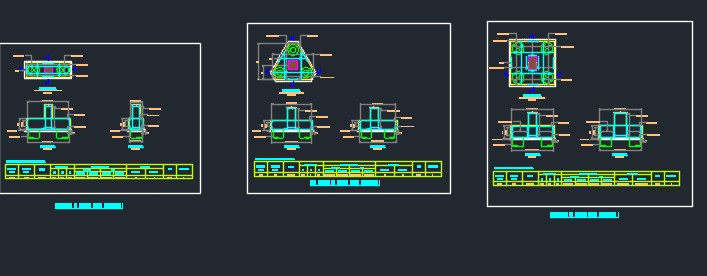
Pile caps are one of the most important components in deep foundation systems. A 3-pile pile cap is commonly used when a single column transfers heavy structural loads to three bored cast-in-situ piles arranged in a triangular pattern.
The drawing shown above represents a 3-pile reinforced concrete pile cap designed to support a centrally placed reinforced concrete column. It includes the pile layout, reinforcement detailing, sectional views, and reinforcement schedule required for construction.
This article explains every part of the drawing and provides practical guidance for engineers, site supervisors, students, and contractors.

What is a Pile Cap?
A pile cap is a thick reinforced concrete member that ties two or more piles together and distributes the load from the column uniformly to the pile group.
The pile cap acts as an intermediate structural element between:
- Superstructure Column
- Foundation Piles
- Soil Bearing System
Without a properly designed pile cap, loads cannot be transferred efficiently, resulting in excessive stresses and differential settlement.
A 3-pile cap is a deep member, so the Strut-and-Tie Model is more appropriate than ordinary beam theory. The column should generally be positioned at the centroid of the pile group to achieve balanced pile reactions. When the load passes through the centroid, each pile ideally carries one-third of the vertical load (neglecting the pile cap’s self-weight). If the column is eccentric, the pile reactions become unequal and additional bending effects must be accounted for. The bottom reinforcement functions as the tension tie, while the concrete carries load through inclined compression struts.
Components Shown in the Drawing
The drawing consists of the following major views:
1. Pile Cap Plan
The plan view shows:
- Three pile locations
- Column position
- Reinforcement direction
- Edge dimensions
- Concrete cover
- Section cutting lines
- Reinforcement spacing
The piles are arranged in a triangular configuration providing equal load distribution.
2. Section A-A
This section illustrates:
- Overall pile cap depth
- Bottom reinforcement
- Top reinforcement
- Column starter bars
- PCC layer
- Pile penetration into cap
- Concrete cover
3. Section B-B
The second section provides:
- Reinforcement in the perpendicular direction
- Bar spacing
- Anchorage
- Development length
- Bottom reinforcement placement
4. Reinforcement Schedule
The schedule provides:
| Item | Description |
|---|---|
| Concrete Grade | M40 |
| Reinforcement Steel | Fe415 |
| Number of Piles | 3 |
| Pile Diameter | 1000 mm |
| Overall Depth | 925 mm |
| Top Reinforcement | T10 @140 mm c/c |
| Bottom Reinforcement | T25 @145–150 mm c/c |
This schedule allows site engineers to fabricate reinforcement accurately
Advantages of 3-Pile Pile Cap
✔ Uniform load distribution
✔ Economical design
✔ High structural stability
✔ Suitable for heavy columns
✔ Reduces differential settlement
✔ Excellent seismic performance
✔ Easy reinforcement detailing
Common Design Checks
Structural engineers generally verify:
- Bearing capacity
- Punching shear
- One-way shear
- Flexural strength
- Strut-and-tie action
- Development length
- Anchorage
- Concrete cover
- Crack width
- Reinforcement spacing
Quality Control Checklist
Before concreting ensure:
- Pile positions verified
- Reinforcement checked
- Bar spacing maintained
- Cover blocks installed
- Column bars vertical
- PCC level completed
- Formwork aligned
- Concrete grade confirmed
- Vibrator available
- Cube samples prepared
Typical Applications
A 3-pile pile cap is widely used in:
- Commercial Buildings
- Industrial Plants
- Steel Structures
- PEB Buildings
- Warehouses
- Bridges
- Water Tanks
- Towers
- Heavy Machine Foundations
- Multi-storey Buildings
Common Construction Mistakes
Avoid these frequent errors:
- Incorrect pile positioning
- Insufficient concrete cover
- Missing top reinforcement
- Improper bar anchorage
- Honeycombing due to poor vibration
- Uneven pile head levels
- Wrong reinforcement spacing
- Inadequate curing
- Improper pile trimming
- Misaligned column starter bars
Best Construction Practices
- Use accurate surveying before excavation.
- Trim pile heads to the specified level.
- Maintain reinforcement cover with approved cover blocks.
- Use the specified concrete grade.
- Vibrate concrete adequately to eliminate voids.
- Cure the pile cap continuously to achieve the desired strength.
- Inspect reinforcement and formwork before pouring concrete.
Conclusion
A 3-pile pile cap is an efficient and reliable foundation element for transferring heavy column loads to a triangular pile group. Proper detailing of reinforcement, correct pile spacing, adequate concrete cover, and thorough quality control are essential for long-term structural performance. The drawing shown illustrates a practical reinforcement layout that helps engineers and site teams execute the foundation safely and accurately.
Frequently Asked Questions (FAQs)
What is a 3-pile pile cap?
It is a reinforced concrete foundation that connects three piles and distributes the load from a single column to the pile group.
Why are three piles arranged in a triangular pattern?
A triangular arrangement provides balanced load distribution, improves stability, and reduces eccentricity.
What concrete grade is used in this drawing?
The schedule specifies M40 concrete.
What reinforcement grade is specified?
The drawing indicates Fe415 reinforcement steel.
What is the purpose of top reinforcement?
Top reinforcement controls shrinkage and temperature cracking and helps resist negative bending moments.
What is the function of the PCC layer?
The 150 mm thick PCC layer provides a clean, level base for reinforcement placement and prevents contamination of structural concrete.
- Pile Cap Detail Drawing Free Download
 Pile caps are one of the most important components in… Read more: Pile Cap Detail Drawing Free Download
 - Splice Details for Angles
 Steel angle sections are one of the most commonly used… Read more: Splice Details for Angles
 - Room Paint Calculator | Quantity and Cost Estimator
 Looking to renovate your room? Our Room Paint, Primer &… Read more: Room Paint Calculator | Quantity and Cost Estimator
 - Manhole Cover Detail
 Manhole covers are one of the most important components in… Read more: Manhole Cover Detail
 - Side Cladding Runner Details for PEB Structures
 Introduction Side cladding runners are one of the most important… Read more: Side Cladding Runner Details for PEB Structures
 - Expansion Joints in Concrete Pavements
 Concrete pavements are designed to withstand heavy traffic loads, temperature… Read more: Expansion Joints in Concrete Pavements
 - RCC Staircase Detail Drawing free pdf Download
 Reinforced Cement Concrete (RCC) staircases are one of the most… Read more: RCC Staircase Detail Drawing free pdf Download
 - Pipe Rack GA Drawing Layout
 Image – Typical Pipe Rack GA Drawing Explanation The above… Read more: Pipe Rack GA Drawing Layout
 - Bund Wall Detail Drawing for Tank Farm and Oil Storage Area
 Introduction A bund wall (also called a dyke wall or… Read more: Bund Wall Detail Drawing for Tank Farm and Oil Storage Area
 - Dyke Wall Layout and Detail | Oil Tank Containment Systems |
 Introduction A dyke wall (also called a bund wall or… Read more: Dyke Wall Layout and Detail | Oil Tank Containment Systems |
 - How to Assign LY and LZ in STAAD for Steel Structures (With and Without Bracing)
 🔹 What is LY and LZ? In STAAD.Pro: These define… Read more: How to Assign LY and LZ in STAAD for Steel Structures (With and Without Bracing)
 - EDG Building Power Cable Layout with MTO Guide
 Introduction An Emergency Diesel Generator (EDG) system is a critical… Read more: EDG Building Power Cable Layout with MTO Guide
 - Septic Tank Drawing and Details
 Septic tanks are widely used in residential buildings for on-site… Read more: Septic Tank Drawing and Details
 - Holding Tank Detail
 Introduction A holding tank, also known as a water sump… Read more: Holding Tank Detail
 - Rain Water Harvesting System pdf Book Download
 TABLE OF CONTENTS 1.0 INTRODUCTION 3 2.0 CHAPTER 1 4… Read more: Rain Water Harvesting System pdf Book Download
 - Galvanized Gate | Design Details and Specifications Guide |
 Introduction Industrial galvanized gates are designed for heavy-duty usage, high… Read more: Galvanized Gate | Design Details and Specifications Guide |
 - Soak Pit Details | Seepage Pit |
 Introduction A soak pit or seepage pit (also called a… Read more: Soak Pit Details | Seepage Pit |
 - Expansion, Contraction and Construction Joints in Concrete for Civil Works
 1. Introduction Concrete is one of the most widely used… Read more: Expansion, Contraction and Construction Joints in Concrete for Civil Works
 - Cable Rack Structural Steel Detail and Design
 Introduction Cable racks (also called cable trays or cable support… Read more: Cable Rack Structural Steel Detail and Design
 - RCC Shear Wall Details
 Introduction Reinforced Cement Concrete (RCC) shear walls are one of… Read more: RCC Shear Wall Details
 - RCC Column with Splice and Coupler in Reinforcement Free Download
 Introduction Reinforced Cement Concrete (RCC) columns are one of the… Read more: RCC Column with Splice and Coupler in Reinforcement Free Download
 - Manhole Types and Details
 Manholes are essential underground structures used in sewer systems, stormwater… Read more: Manhole Types and Details
 - Catch Basin Types and Details
 Catch basins are essential components of stormwater management systems. They… Read more: Catch Basin Types and Details
 - Foundation Detail Drawings for Buildings With CAD Files
 A Practical Structural Drawing Guide Introduction Footing drawings form the… Read more: Foundation Detail Drawings for Buildings With CAD Files
 - Bar Bending Schedule | BBS Calculator For Beam Column and Slab
 Managing the Bar Bending Schedule (BBS) is one of the… Read more: Bar Bending Schedule | BBS Calculator For Beam Column and Slab
Leave a Reply