
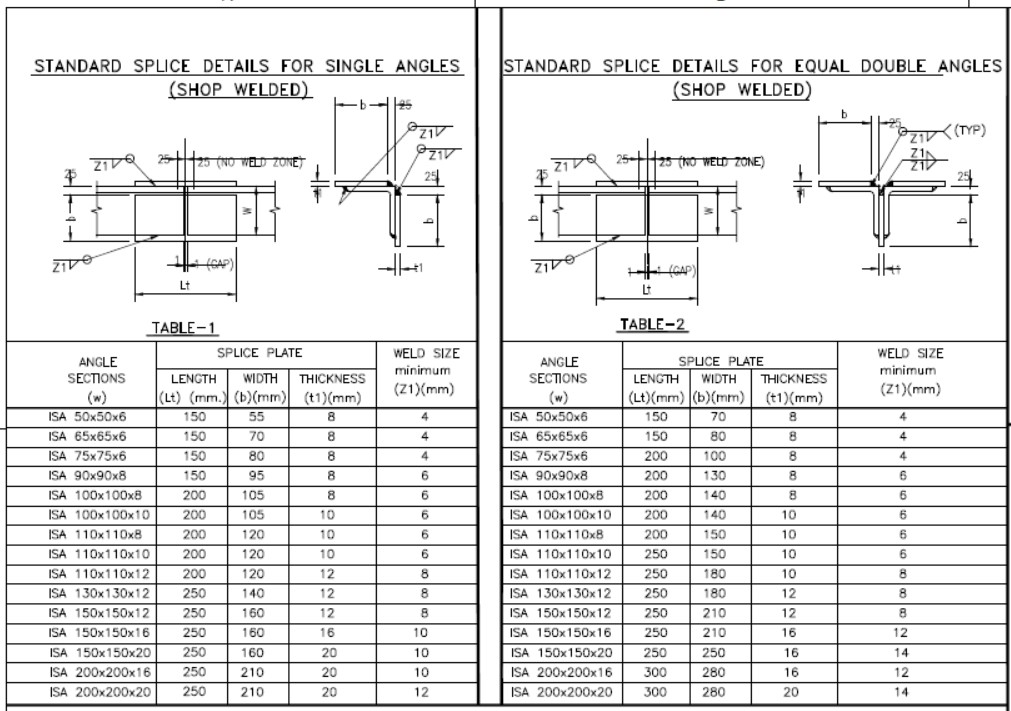
Steel angle sections are one of the most commonly used structural members in industrial buildings, transmission towers, trusses, pipe racks, conveyors, platforms, staircases, and PEB (Pre-Engineered Buildings). When the available member length is insufficient or transportation limitations exist, splice connections are provided to safely transfer axial forces between two angle members.
The drawing shown above illustrates the standard shop welded splice details for both:
- Single Angle Sections
- Equal Double Angle Sections
These standard details simplify fabrication while ensuring adequate structural performance.

What is an Angle Splice?
A splice is the connection made between two structural members to create one continuous member.
For angle sections, a steel splice plate is welded over the joint so that the load is transferred through the welds and splice plate instead of directly through the angle ends.
The connection is generally designed to transfer:
- Axial Tension
- Axial Compression
- Minor Bending
- Shear Forces
Types of Standard Angle Splices
1. Single Angle Splice (Shop Welded)
A single steel angle is connected using one splice plate placed over the angle leg.
Features
- Single splice plate
- Continuous shop welding
- No weld zone maintained near splice center
- Suitable for axial members
- Economical fabrication
Typical applications include:
- Roof Bracing
- Vertical Bracing
- Pipe Supports
- Ladders
- Light Steel Frames
2. Equal Double Angle Splice (Shop Welded)
For double angles placed back-to-back, a larger splice plate is used to connect both angle sections.
Advantages
- Higher load carrying capacity
- Better load distribution
- Increased stiffness
- Reduced eccentricity
- Suitable for heavy industrial structures
Common applications include:
- Truss Members
- Crane Structures
- Transmission Towers
- Industrial Pipe Racks
- Conveyor Galleries
Components of a Standard Angle Splice
The splice connection consists of the following parts:
Angle Section
The primary structural member carrying the applied load.
Examples include:
- ISA 50×50×6
- ISA 65×65×6
- ISA 75×75×6
- ISA 100×100×10
- ISA 150×150×16
- ISA 200×200×20
Splice Plate
A flat steel plate welded over the splice.
Its dimensions are selected based on:
- Angle size
- Load
- Required weld length
- Plate thickness
- Fabrication standards
Weld
The splice plate is connected using continuous fillet welds.
Typical weld sizes shown include:
- 4 mm
- 6 mm
- 8 mm
- 10 mm
- 12 mm
- 14 mm
No Weld Zone
The drawing indicates a 25 mm no-weld zone around the splice center.
Purpose:
- Reduces heat concentration
- Minimizes welding distortion
- Prevents excessive residual stresses
- Improves fabrication quality
Standard Splice Plate Dimensions
The drawing provides recommended splice plate dimensions based on the angle size.
Typical parameters include:
- Lt – Splice plate length
- b – Plate width
- t1 – Plate thickness
- Z1 – Minimum weld size
As the angle size increases:
- Plate length increases
- Plate width increases
- Plate thickness increases
- Weld size increases
This ensures the splice develops the required member strength.
Weld Size Recommendations
Typical minimum weld sizes are:
| Angle Size | Minimum Weld |
|---|---|
| Small Angles | 4 mm |
| Medium Angles | 6 mm |
| Heavy Angles | 8 mm |
| Large Industrial Angles | 10–14 mm |
Actual weld sizes should always be verified by structural design calculations in accordance with the governing design code.
Design Considerations
When designing an angle splice, engineers should verify:
- Axial load capacity
- Net section strength
- Gross section yielding
- Weld strength
- Plate bending
- Block shear
- Eccentric loading
- Buckling (compression members)
- Fatigue (cyclic loading)
- Corrosion allowance (if applicable)
Advantages of Shop Welded Splices
✔ Better fabrication quality
✔ Accurate alignment
✔ Reduced erection time
✔ Lower site welding requirements
✔ Improved dimensional accuracy
✔ Consistent weld quality
✔ Faster project execution
Applications
These standard splice details are widely used in:
- Pre-Engineered Buildings (PEB)
- Industrial Steel Structures
- Warehouse Buildings
- Power Plants
- Cement Plants
- Refineries
- Petrochemical Plants
- Pipe Racks
- Conveyor Structures
- Roof Trusses
- Steel Towers
- Mezzanine Floors
- Stair Towers
- Equipment Supports
Fabrication Guidelines
For best performance:
- Clean all steel surfaces before welding.
- Maintain proper root alignment.
- Follow qualified welding procedures (WPS).
- Use certified welders.
- Perform dimensional checks before welding.
- Inspect welds visually and by NDT if required.
- Apply corrosion protection after fabrication.
Inspection Checklist
Before accepting the splice:
- Plate dimensions verified
- Correct plate thickness
- Correct weld size
- Continuous welds completed
- No cracks
- No excessive undercut
- Proper alignment maintained
- No visible distortion
- Weld length as per drawing
- Surface cleaned and painted
Relevant Design Codes
Depending on the project location, splice design should comply with:
- IS 800:2007 – General Construction in Steel (India)
- AWS D1.1 – Structural Welding Code – Steel
- AISC 360 – Specification for Structural Steel Buildings
- Eurocode 3 (EN 1993) – Design of Steel Structures
- AS 4100 – Steel Structures (Australia)
- CSA S16 – Design of Steel Structures (Canada)
Best Practices
- Avoid placing splices at locations of maximum bending moment where possible.
- Use shop welding instead of field welding whenever practical.
- Ensure splice plates are centered correctly.
- Follow minimum edge distances and weld clearances.
- Protect welded joints with primer and finish coatings.
- Verify fit-up before final welding to minimize residual stresses.
Conclusion
Standard shop welded splice details for single and equal double angle sections provide a reliable and efficient method for extending structural steel members while maintaining load transfer and structural integrity. By selecting appropriate splice plate dimensions, weld sizes, and following recognized design codes such as IS 800, AISC, AWS, and Eurocode, engineers can ensure safe, durable, and economical steel connections for a wide range of industrial and commercial projects.
- Splice Details for Angles
 Steel angle sections are one of the most commonly used… Read more: Splice Details for Angles
 - Room Paint Calculator | Quantity and Cost Estimator
 Looking to renovate your room? Our Room Paint, Primer &… Read more: Room Paint Calculator | Quantity and Cost Estimator
 - Manhole Cover Detail
 Manhole covers are one of the most important components in… Read more: Manhole Cover Detail
 - Side Cladding Runner Details for PEB Structures
 Introduction Side cladding runners are one of the most important… Read more: Side Cladding Runner Details for PEB Structures
 - Expansion Joints in Concrete Pavements
 Concrete pavements are designed to withstand heavy traffic loads, temperature… Read more: Expansion Joints in Concrete Pavements
 - RCC Staircase Detail Drawing free pdf Download
 Reinforced Cement Concrete (RCC) staircases are one of the most… Read more: RCC Staircase Detail Drawing free pdf Download
 - Pipe Rack GA Drawing Layout
 Image – Typical Pipe Rack GA Drawing Explanation The above… Read more: Pipe Rack GA Drawing Layout
 - Bund Wall Detail Drawing for Tank Farm and Oil Storage Area
 Introduction A bund wall (also called a dyke wall or… Read more: Bund Wall Detail Drawing for Tank Farm and Oil Storage Area
 - Dyke Wall Layout and Detail | Oil Tank Containment Systems |
 Introduction A dyke wall (also called a bund wall or… Read more: Dyke Wall Layout and Detail | Oil Tank Containment Systems |
 - How to Assign LY and LZ in STAAD for Steel Structures (With and Without Bracing)
 🔹 What is LY and LZ? In STAAD.Pro: These define… Read more: How to Assign LY and LZ in STAAD for Steel Structures (With and Without Bracing)
 - EDG Building Power Cable Layout with MTO Guide
 Introduction An Emergency Diesel Generator (EDG) system is a critical… Read more: EDG Building Power Cable Layout with MTO Guide
 - Septic Tank Drawing and Details
 Septic tanks are widely used in residential buildings for on-site… Read more: Septic Tank Drawing and Details
 - Holding Tank Detail
 Introduction A holding tank, also known as a water sump… Read more: Holding Tank Detail
 - Rain Water Harvesting System pdf Book Download
 TABLE OF CONTENTS 1.0 INTRODUCTION 3 2.0 CHAPTER 1 4… Read more: Rain Water Harvesting System pdf Book Download
 - Galvanized Gate | Design Details and Specifications Guide |
 Introduction Industrial galvanized gates are designed for heavy-duty usage, high… Read more: Galvanized Gate | Design Details and Specifications Guide |
 - Soak Pit Details | Seepage Pit |
 Introduction A soak pit or seepage pit (also called a… Read more: Soak Pit Details | Seepage Pit |
 - Expansion, Contraction and Construction Joints in Concrete for Civil Works
 1. Introduction Concrete is one of the most widely used… Read more: Expansion, Contraction and Construction Joints in Concrete for Civil Works
 - Cable Rack Structural Steel Detail and Design
 Introduction Cable racks (also called cable trays or cable support… Read more: Cable Rack Structural Steel Detail and Design
 - RCC Shear Wall Details
 Introduction Reinforced Cement Concrete (RCC) shear walls are one of… Read more: RCC Shear Wall Details
 - RCC Column with Splice and Coupler in Reinforcement Free Download
 Introduction Reinforced Cement Concrete (RCC) columns are one of the… Read more: RCC Column with Splice and Coupler in Reinforcement Free Download
 - Manhole Types and Details
 Manholes are essential underground structures used in sewer systems, stormwater… Read more: Manhole Types and Details
 - Catch Basin Types and Details
 Catch basins are essential components of stormwater management systems. They… Read more: Catch Basin Types and Details
 - Foundation Detail Drawings for Buildings With CAD Files
 A Practical Structural Drawing Guide Introduction Footing drawings form the… Read more: Foundation Detail Drawings for Buildings With CAD Files
 - Bar Bending Schedule | BBS Calculator For Beam Column and Slab
 Managing the Bar Bending Schedule (BBS) is one of the… Read more: Bar Bending Schedule | BBS Calculator For Beam Column and Slab
 - Brick Wall Construction Calculator | Calculate Bricks & Cost Instantly |
 Introduction Building a brick wall requires accurate planning to avoid… Read more: Brick Wall Construction Calculator | Calculate Bricks & Cost Instantly |
Leave a Reply