
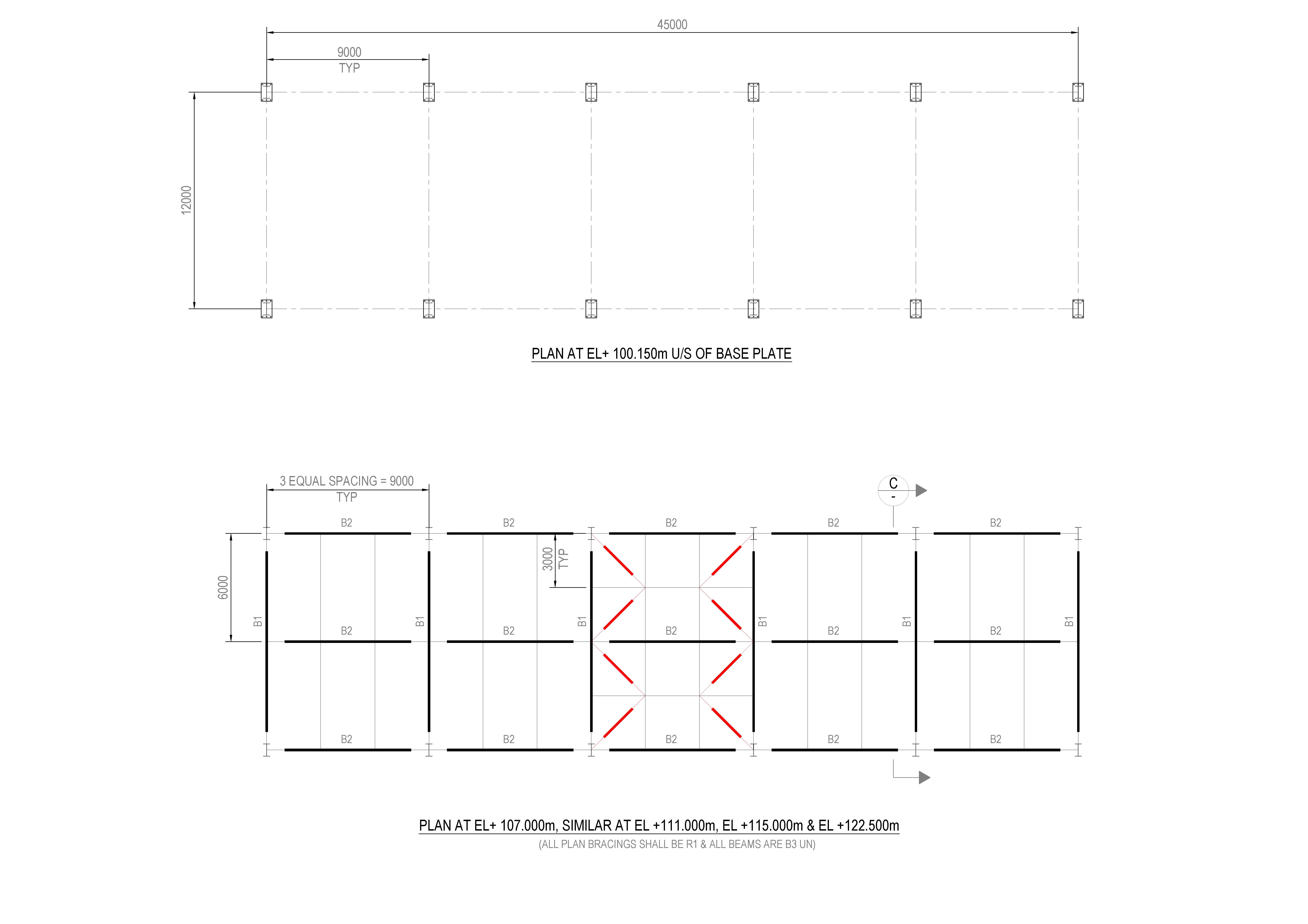
Image – Typical Pipe Rack GA Drawing
Explanation
The above GA drawing generally contains:
- Structural grid lines
- Column numbering system
- Longitudinal beams
- Transverse beams
- Bracing bays
- Pipe support elevations
- Expansion joint locations
- Walkway arrangement
- Cable tray support structure


Understanding Structural Grid Lines
Grid lines are reference lines used for identifying structural member positions.
Image – Structural Grid Layout
Grid System Example
| Direction | Example |
|---|---|
| Longitudinal | 1, 2, 3, 4 |
| Transverse | A, B, C |
Columns are identified at intersections such as:
- A1
- B2
- C3
This system simplifies fabrication and erection activities.
Pipe Rack Column Arrangement
Columns are the primary vertical load-carrying members.
Image – Pipe Rack Column Arrangement
Column Functions
Pipe rack columns support:
- Structural beams
- Pipe loads
- Cable trays
- Walkways
- Wind and seismic forces
Common Column Sections
- ISMB Sections
- H-Beams
- Box Sections
- Built-up Steel Columns
Typical Column Spacing
Usually:
- 6m
- 8m
- 10m
Spacing depends on:
- Pipe load
- Pipe diameter
- Utility congestion
- Structural analysis
Beam Arrangement in Pipe Rack Structure
Beams transfer loads from pipes and supports to columns.
Image – Pipe Rack Beam Layout
Types of Beams
1. Longitudinal Beams
These beams run along the length of the pipe rack.
Function
- Support pipe loads
- Connect columns
- Transfer loads longitudinally
2. Transverse Beams
These beams run across the width of the rack.
Function
- Support pipe tiers
- Carry cable trays
- Stabilize the structure
Pipe Rack Bracing System Explained
Bracing is one of the most critical elements in pipe rack structures.
Bracing prevents excessive movement caused by:
- Wind loads
- Earthquake forces
- Pipe vibration
- Thermal movement
Vertical Bracing in Pipe Rack
Vertical bracing is installed between columns.
Image – Vertical X Bracing
Purpose of Vertical Bracing
- Prevent side sway
- Improve lateral stability
- Resist wind forces
- Reduce vibration
Common Vertical Bracing Types
| Bracing Type | Application |
| X-Bracing | Most common industrial application |
| K-Bracing | Where pipe clearance required |
| Single Diagonal | Small structures |
Typical Bracing Locations
Bracing is generally provided:
- At end bays
- Every 4th or 5th bay
- Near expansion joints
- Heavy pipe load zones
- Equipment connection areas
Image – Bracing Bay Locations
Example
| Bay Number | Bracing |
| Bay 1 | X-Bracing |
| Bay 5 | X-Bracing |
| Bay 10 | Expansion Joint |
| Bay 11 | Bracing |
| End Bay | Full Bracing |
Longitudinal Bracing Explanation
Longitudinal bracing runs along the pipe rack direction.
Image – Longitudinal Bracing
Purpose
- Resist longitudinal movement
- Improve seismic resistance
- Transfer structural forces
- Maintain frame alignment
Horizontal Bracing System
Horizontal bracing is installed at beam levels.
Image – Horizontal Bracing Layout
Purpose
- Stabilize top beams
- Support cable tray levels
- Maintain structural geometry
Pipe Rack Elevation Drawing Explanation
Elevation drawings show the vertical view of the structure.
Image – Pipe Rack Elevation Drawing
Elevation Drawing Includes
- Column heights
- Beam levels
- Pipe support elevations
- Bracing arrangement
- Foundation top levels
- Walkway positions
Pipe Rack Expansion Joint Details
Pipe racks expand and contract due to temperature changes.
Expansion joints are provided to absorb thermal movement.
Image – Pipe Rack Expansion Joint
Expansion Joint Locations
Generally provided every:
- 30m to 60m
Depending on:
- Temperature variation
- Pipe stress analysis
- Structural design criteria
Pipe Rack Foundation Drawing Explanation
The foundation transfers structural loads safely to the soil.
Image – Pipe Rack Foundation Detail
Foundation Drawing Includes
- Footing size
- Pedestal dimensions
- Reinforcement details
- Anchor bolt arrangement
- Base plate details
- Foundation depth
Structural Connection Details
Connections are critical for structural stability.
Image – Beam to Column Connection
Connection Components
- Gusset plates
- Anchor bolts
- Weld joints
- Splice plates
- Stiffener plates
Pipe Rack Load Calculations
Structural engineers consider multiple loads during design.
1. Dead Load
Includes:
- Steel self-weight
- Pipe weight
- Cable trays
2. Operating Load
Includes:
- Fluid-filled pipes
- Insulation loads
- Maintenance loads
3. Hydrotest Load
Temporary water-filled pipe load during testing.
This is often higher than operating load.
4. Wind Load
Wind force affects:
- Bracing design
- Column sizing
- Foundation stability
5. Seismic Load
Earthquake analysis ensures structural safety in seismic zones.
Pipe Rack Fabrication Process
Step 1 – Steel Cutting
Structural members are cut according to fabrication drawings.
Step 2 – Drilling & Welding
Bolt holes and weld preparations are completed.
Step 3 – Surface Treatment
Sand blasting and painting performed.
Step 4 – Trial Assembly
Dimensional accuracy checked before dispatch.
Step 5 – Site Erection
Columns, beams, and bracings are erected using cranes.
Advantages of Proper Pipe Rack Structural Design
Benefits
✅ Improved plant safety
✅ Better utility management
✅ Reduced pipe stress
✅ Better earthquake resistance
✅ Improved wind stability
✅ Easy maintenance access
✅ Future expansion flexibility
Common Problems Without Proper Bracing
Without adequate bracing:
- Excessive sway occurs
- Pipe vibration increases
- Structural instability develops
- Beam deflection becomes excessive
- Connection failure risk increases
Software Used for Pipe Rack Design
Industrial projects commonly use:
- STAAD Pro
- ETABS
- Tekla Structures
- AutoCAD
- Revit
- Navisworks
These software platforms improve:
- Structural analysis
- Clash detection
- Fabrication accuracy
- 3D coordination
Conclusion
Pipe Rack Structural GA Drawings are essential engineering documents in industrial construction projects. They provide complete information regarding structural layout, beam arrangement, bracing systems, pipe support levels, and foundation details.
Among all structural elements, the bracing system plays the most important role in ensuring structural stability against wind, seismic forces, vibration, and thermal movement.
A properly designed pipe rack structure improves:
- Plant safety
- Structural durability
- Construction quality
- Future maintenance access
- Overall project efficiency
Modern industrial projects increasingly depend on 3D structural modeling and BIM coordination for accurate execution and reduced site errors.
- Side Cladding Runner Details for PEB Structures
 Introduction Side cladding runners are one of the most important… Read more: Side Cladding Runner Details for PEB Structures
 - Expansion Joints in Concrete Pavements
 Concrete pavements are designed to withstand heavy traffic loads, temperature… Read more: Expansion Joints in Concrete Pavements
 - RCC Staircase Detail Drawing free pdf Download
 Reinforced Cement Concrete (RCC) staircases are one of the most… Read more: RCC Staircase Detail Drawing free pdf Download
 - Pipe Rack GA Drawing Layout
 Image – Typical Pipe Rack GA Drawing Explanation The above… Read more: Pipe Rack GA Drawing Layout
 - Bund Wall Detail Drawing for Tank Farm and Oil Storage Area
 Introduction A bund wall (also called a dyke wall or… Read more: Bund Wall Detail Drawing for Tank Farm and Oil Storage Area
 - Dyke Wall Layout and Detail | Oil Tank Containment Systems |
 Introduction A dyke wall (also called a bund wall or… Read more: Dyke Wall Layout and Detail | Oil Tank Containment Systems |
 - How to Assign LY and LZ in STAAD for Steel Structures (With and Without Bracing)
 🔹 What is LY and LZ? In STAAD.Pro: These define… Read more: How to Assign LY and LZ in STAAD for Steel Structures (With and Without Bracing)
 - EDG Building Power Cable Layout with MTO Guide
 Introduction An Emergency Diesel Generator (EDG) system is a critical… Read more: EDG Building Power Cable Layout with MTO Guide
 - Septic Tank Drawing and Details
 Septic tanks are widely used in residential buildings for on-site… Read more: Septic Tank Drawing and Details
 - Holding Tank Detail
 Introduction A holding tank, also known as a water sump… Read more: Holding Tank Detail
 - Rain Water Harvesting System pdf Book Download
 TABLE OF CONTENTS 1.0 INTRODUCTION 3 2.0 CHAPTER 1 4… Read more: Rain Water Harvesting System pdf Book Download
 - Galvanized Gate | Design Details and Specifications Guide |
 Introduction Industrial galvanized gates are designed for heavy-duty usage, high… Read more: Galvanized Gate | Design Details and Specifications Guide |
 - Soak Pit Details | Seepage Pit |
 Introduction A soak pit or seepage pit (also called a… Read more: Soak Pit Details | Seepage Pit |
 - Expansion, Contraction and Construction Joints in Concrete for Civil Works
 1. Introduction Concrete is one of the most widely used… Read more: Expansion, Contraction and Construction Joints in Concrete for Civil Works
 - Cable Rack Structural Steel Detail and Design
 Introduction Cable racks (also called cable trays or cable support… Read more: Cable Rack Structural Steel Detail and Design
 - RCC Shear Wall Details
 Introduction Reinforced Cement Concrete (RCC) shear walls are one of… Read more: RCC Shear Wall Details
 - RCC Column with Splice and Coupler in Reinforcement Free Download
 Introduction Reinforced Cement Concrete (RCC) columns are one of the… Read more: RCC Column with Splice and Coupler in Reinforcement Free Download
 - Manhole Types and Details
 Manholes are essential underground structures used in sewer systems, stormwater… Read more: Manhole Types and Details
 - Catch Basin Types and Details
 Catch basins are essential components of stormwater management systems. They… Read more: Catch Basin Types and Details
 - Foundation Detail Drawings for Buildings With CAD Files
 A Practical Structural Drawing Guide Introduction Footing drawings form the… Read more: Foundation Detail Drawings for Buildings With CAD Files
 - Bar Bending Schedule | BBS Calculator For Beam Column and Slab
 Managing the Bar Bending Schedule (BBS) is one of the… Read more: Bar Bending Schedule | BBS Calculator For Beam Column and Slab
 - Room Paint Calculator | Paint, Primer & Putty Quantity & Cost Estimator
 Looking to renovate your room? Our Room Paint, Primer &… Read more: Room Paint Calculator | Paint, Primer & Putty Quantity & Cost Estimator
 - Brick Wall Construction Calculator | Calculate Bricks & Cost Instantly |
 Introduction Building a brick wall requires accurate planning to avoid… Read more: Brick Wall Construction Calculator | Calculate Bricks & Cost Instantly |
 - Unit Converter – Feet, Inches, cm, mm, Yard to Meter and Vice Versa
 Length Unit Converter 🌙 Toggle Dark Mode Length Unit Converter… Read more: Unit Converter – Feet, Inches, cm, mm, Yard to Meter and Vice Versa
 - Civil Engineering Interview Questions and Important Practical Foundation
 1. What factors affect the selection of foundation type? Soil… Read more: Civil Engineering Interview Questions and Important Practical Foundation