
Introduction
An Emergency Diesel Generator (EDG) system is a critical backup power source used in industrial plants, commercial buildings, and infrastructure facilities. Proper power cable layout design ensures safety, reliability, and uninterrupted power supply during outages.
This article explains the EDG room cable routing, equipment arrangement, installation practices, and a detailed Material Take-Off (MTO) based on the provided drawing.
Overview of EDG Room Layout
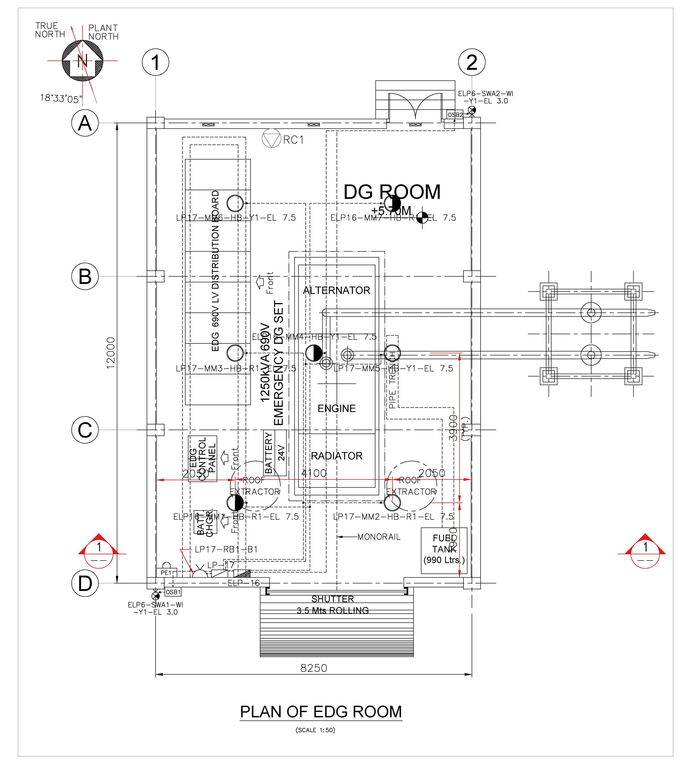
The attached plan shows a dedicated DG Room housing:
- 1250 kVA Emergency DG Set
- Alternator + Engine + Radiator assembly
- LV Distribution Board (690V)
- Control Panel
- Battery Bank (24V)
- Fuel Tank (990 Litres)
- Cable routing trench with monorail support
- Ventilation system (Roof Extractors)


Room Dimensions
- Approx Size: 12,000 mm (L) × 8,250 mm (W)
- Clear working space provided around DG set for maintenance
Power Cable Layout Description
1. Cable Routing Path
- Power cables originate from the Alternator output
- Routed through underground cable trench
- Enter the LV Distribution Board (EDG 690V Panel)
- Outgoing feeders distributed to loads
2. Cable Tray System
- Heavy-duty MS cable trays used inside trench
- Supported on:
- Concrete pedestals
- Monorail structure for maintenance lifting
3. Entry & Exit Points
- Cables enter/exit via:
- Wall sleeves
- Cable glands at panels
- Proper sealing ensures:
- Fire safety
- Dust/moisture protection
4. Separation of Cables
- Power cables separated from:
- Control cables
- Instrumentation lines
- Avoids electromagnetic interference (EMI)
Electrical Components in Layout
DG Set
- Capacity: 1250 kVA
- Voltage: 690V
- Main source during emergency
LV Distribution Board
- Receives DG output
- Feeds:
- Critical loads
- Emergency systems
Battery System
- 24V system for:
- DG starting
- Control circuits
Control Panel
- DG synchronization & monitoring
- Protection systems included
Cable Installation Method
Step-by-Step Execution
- Marking & trench preparation
- Installation of cable tray supports
- Fixing cable trays
- Cable pulling using rollers
- Glanding & termination
- Megger testing
- Earthing & bonding
- Final commissioning
Safety Considerations
- Fire-retardant cables (FRLS/XLPE)
- Proper earthing for all equipment
- Cable tagging and identification
- Adequate ventilation in DG room
- Oil-resistant cable routing near engine
Material Take-Off (MTO)
1. Power Cables
| Description | Size | Qty (Approx) | Unit |
|---|---|---|---|
| DG to LV Panel Cable | 3.5C x 630 sq.mm XLPE | 40–60 | Meter |
| Control Cable | 12C x 2.5 sq.mm | 30–50 | Meter |
2. Cable Tray System
| Description | Size | Qty | Unit |
|---|---|---|---|
| MS Cable Tray (Perforated) | 600 mm width | 25–30 | Meter |
| Tray Covers | Matching | 25–30 | Meter |
| Tray Supports | MS Angle | 20–25 | Nos |
3. Cable Accessories
| Item | Qty |
|---|---|
| Cable Glands (Double Compression) | 20–30 Nos |
| Copper Lugs | 50–80 Nos |
| Heat Shrink Sleeves | As required |
| Ferrules & Tags | Bulk |
4. Earthing Materials
| Item | Qty |
|---|---|
| GI Strip (50×6 mm) | 30–40 m |
| Earth Pits | 2–3 Nos |
| Earthing Clamps | As required |
5. Civil & Structural
| Item | Qty |
|---|---|
| Cable Trench Concrete | As per length |
| RCC Supports | 15–20 Nos |
| Monorail Beam | 1 Set |
6. Miscellaneous
- Cable markers
- Warning tapes
- Fire sealant
- Cable ties
Best Practices for EDG Cable Layout
- Maintain minimum bending radius
- Avoid cable crossing wherever possible
- Use segregated routing for power/control
- Ensure future expansion space
- Provide drainage in cable trench
Conclusion
A well-designed EDG power cable layout ensures:
- Reliable emergency power supply
- Reduced maintenance issues
- Enhanced safety and compliance
The provided layout demonstrates a professional industrial standard design, integrating electrical, mechanical, and civil aspects efficiently.
- Side Cladding Runner Details for PEB Structures
 Introduction Side cladding runners are one of the most important… Read more: Side Cladding Runner Details for PEB Structures
 - Expansion Joints in Concrete Pavements
 Concrete pavements are designed to withstand heavy traffic loads, temperature… Read more: Expansion Joints in Concrete Pavements
 - RCC Staircase Detail Drawing free pdf Download
 Reinforced Cement Concrete (RCC) staircases are one of the most… Read more: RCC Staircase Detail Drawing free pdf Download
 - Pipe Rack GA Drawing Layout
 Image – Typical Pipe Rack GA Drawing Explanation The above… Read more: Pipe Rack GA Drawing Layout
 - Bund Wall Detail Drawing for Tank Farm and Oil Storage Area
 Introduction A bund wall (also called a dyke wall or… Read more: Bund Wall Detail Drawing for Tank Farm and Oil Storage Area
 - Dyke Wall Layout and Detail | Oil Tank Containment Systems |
 Introduction A dyke wall (also called a bund wall or… Read more: Dyke Wall Layout and Detail | Oil Tank Containment Systems |
 - How to Assign LY and LZ in STAAD for Steel Structures (With and Without Bracing)
 🔹 What is LY and LZ? In STAAD.Pro: These define… Read more: How to Assign LY and LZ in STAAD for Steel Structures (With and Without Bracing)
 - EDG Building Power Cable Layout with MTO Guide
 Introduction An Emergency Diesel Generator (EDG) system is a critical… Read more: EDG Building Power Cable Layout with MTO Guide
 - Septic Tank Drawing and Details
 Septic tanks are widely used in residential buildings for on-site… Read more: Septic Tank Drawing and Details
 - Holding Tank Detail
 Introduction A holding tank, also known as a water sump… Read more: Holding Tank Detail
 - Rain Water Harvesting System pdf Book Download
 TABLE OF CONTENTS 1.0 INTRODUCTION 3 2.0 CHAPTER 1 4… Read more: Rain Water Harvesting System pdf Book Download
 - Galvanized Gate | Design Details and Specifications Guide |
 Introduction Industrial galvanized gates are designed for heavy-duty usage, high… Read more: Galvanized Gate | Design Details and Specifications Guide |
 - Soak Pit Details | Seepage Pit |
 Introduction A soak pit or seepage pit (also called a… Read more: Soak Pit Details | Seepage Pit |
 - Expansion, Contraction and Construction Joints in Concrete for Civil Works
 1. Introduction Concrete is one of the most widely used… Read more: Expansion, Contraction and Construction Joints in Concrete for Civil Works
 - Cable Rack Structural Steel Detail and Design
 Introduction Cable racks (also called cable trays or cable support… Read more: Cable Rack Structural Steel Detail and Design
 - RCC Shear Wall Details
 Introduction Reinforced Cement Concrete (RCC) shear walls are one of… Read more: RCC Shear Wall Details
 - RCC Column with Splice and Coupler in Reinforcement Free Download
 Introduction Reinforced Cement Concrete (RCC) columns are one of the… Read more: RCC Column with Splice and Coupler in Reinforcement Free Download
 - Manhole Types and Details
 Manholes are essential underground structures used in sewer systems, stormwater… Read more: Manhole Types and Details
 - Catch Basin Types and Details
 Catch basins are essential components of stormwater management systems. They… Read more: Catch Basin Types and Details
 - Foundation Detail Drawings for Buildings With CAD Files
 A Practical Structural Drawing Guide Introduction Footing drawings form the… Read more: Foundation Detail Drawings for Buildings With CAD Files
 - Bar Bending Schedule | BBS Calculator For Beam Column and Slab
 Managing the Bar Bending Schedule (BBS) is one of the… Read more: Bar Bending Schedule | BBS Calculator For Beam Column and Slab
 - Room Paint Calculator | Paint, Primer & Putty Quantity & Cost Estimator
 Looking to renovate your room? Our Room Paint, Primer &… Read more: Room Paint Calculator | Paint, Primer & Putty Quantity & Cost Estimator
 - Brick Wall Construction Calculator | Calculate Bricks & Cost Instantly |
 Introduction Building a brick wall requires accurate planning to avoid… Read more: Brick Wall Construction Calculator | Calculate Bricks & Cost Instantly |
 - Unit Converter – Feet, Inches, cm, mm, Yard to Meter and Vice Versa
 Length Unit Converter 🌙 Toggle Dark Mode Length Unit Converter… Read more: Unit Converter – Feet, Inches, cm, mm, Yard to Meter and Vice Versa
 - Civil Engineering Interview Questions and Important Practical Foundation
 1. What factors affect the selection of foundation type? Soil… Read more: Civil Engineering Interview Questions and Important Practical Foundation
Related Posts: