
Introduction
A holding tank, also known as a water sump tank or underground storage tank, is an essential structure used to store water for domestic, commercial, and industrial purposes. It ensures a continuous water supply, especially in areas with irregular water availability.
This guide explains design principles, construction details, reinforcement, and best practices based on real engineering drawings.


What is a Holding Tank?
A holding tank is a watertight reinforced concrete structure designed to:
- Store potable or non-potable water
- Maintain water pressure stability
- Support pumping systems
- Act as a buffer during supply interruptions

Types of Holding Tanks
1. Underground Holding Tank
- Most common in residential buildings
- Protected from temperature variations
- Requires waterproofing
2. Overhead Tank
- Located at terrace level
- Provides gravity-based water supply
3. Industrial Holding Tank
- Used in factories and treatment plants
- Larger capacity with heavy reinforcement
Key Components of a Holding Tank
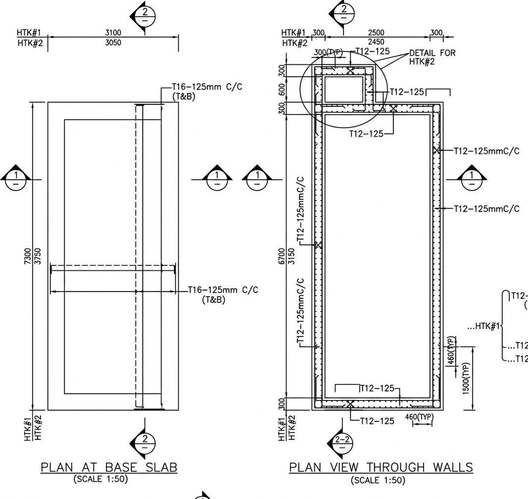
1. Base Slab
- Reinforced concrete slab
- Designed to resist soil pressure and water load
- Reinforcement: typically T12 @ 125mm c/c both ways
2. Side Walls
- Retain water pressure
- Reinforced with vertical and horizontal steel bars
- Thickness depends on depth and capacity
3. Partition / Chamber
- Optional internal chamber for sedimentation or pump housing
- Improves maintenance and water quality
4. Cover Slab
- Precast or cast-in-situ slab
- Includes manhole opening for access
- Reinforced with top and bottom steel
5. Inlet & Outlet Pipes
- Inlet for water supply
- Outlet connected to pump or distribution system
Typical Dimensions (Example from Your Drawing)
- Length: ~3050 mm
- Width: ~1500 mm
- Depth: ~2500 mm
- Chamber height variation included
Dimensions vary based on water demand and site conditions.
Reinforcement Details
Base Slab
- Bottom reinforcement: T12 @ 125mm c/c
- Top reinforcement (if required): T10/T12
Walls
- Vertical bars: T12 @ 125mm c/c
- Horizontal distribution bars: T12 @ 125mm c/c
Cover Slab
- Top & bottom mesh reinforcement
- Extra bars around manhole opening
Construction Procedure
Step 1: Excavation
- Excavate to required depth
- Provide proper shoring if needed
Step 2: PCC (Plain Cement Concrete)
- 75–100 mm thick PCC layer
- Provides level base
Step 3: Reinforcement & Formwork
- Fix steel reinforcement as per drawing
- Provide proper cover blocks
Step 4: Concreting
- Use M20/M25 grade concrete
- Ensure vibration for compaction
Step 5: Waterproofing
- Apply waterproof coating
- Use integral waterproofing compound
Step 6: Curing
- Minimum 7–14 days curing
- Prevents cracks and leakage
Waterproofing Methods
- Integral waterproofing admixture
- External membrane coating
- Internal cementitious coating
- Joint sealing with water stops
Design Considerations
1. Load Factors
- Water pressure
- Soil pressure
- Uplift pressure (important in high water table areas)
2. Crack Control
- Provide proper reinforcement spacing
- Use construction joints carefully
3. Durability
- Use minimum M20 grade concrete
- Ensure proper cover to reinforcement
Advantages of Holding Tanks
- Reliable water storage
- Cost-effective solution
- Low maintenance
- Long lifespan (30+ years with proper construction)
Common Mistakes to Avoid
- Poor waterproofing
- Inadequate reinforcement
- Improper curing
- No expansion joints
- Weak cover slab design
Maintenance Tips
- Clean tank every 3–6 months
- Check for cracks or leakage
- Inspect inlet/outlet pipes
- Ensure proper cover slab sealing
- Side Cladding Runner Details for PEB Structures
 Introduction Side cladding runners are one of the most important… Read more: Side Cladding Runner Details for PEB Structures
 - Expansion Joints in Concrete Pavements
 Concrete pavements are designed to withstand heavy traffic loads, temperature… Read more: Expansion Joints in Concrete Pavements
 - RCC Staircase Detail Drawing free pdf Download
 Reinforced Cement Concrete (RCC) staircases are one of the most… Read more: RCC Staircase Detail Drawing free pdf Download
 - Pipe Rack GA Drawing Layout
 Image – Typical Pipe Rack GA Drawing Explanation The above… Read more: Pipe Rack GA Drawing Layout
 - Bund Wall Detail Drawing for Tank Farm and Oil Storage Area
 Introduction A bund wall (also called a dyke wall or… Read more: Bund Wall Detail Drawing for Tank Farm and Oil Storage Area
 - Dyke Wall Layout and Detail | Oil Tank Containment Systems |
 Introduction A dyke wall (also called a bund wall or… Read more: Dyke Wall Layout and Detail | Oil Tank Containment Systems |
 - How to Assign LY and LZ in STAAD for Steel Structures (With and Without Bracing)
 🔹 What is LY and LZ? In STAAD.Pro: These define… Read more: How to Assign LY and LZ in STAAD for Steel Structures (With and Without Bracing)
 - EDG Building Power Cable Layout with MTO Guide
 Introduction An Emergency Diesel Generator (EDG) system is a critical… Read more: EDG Building Power Cable Layout with MTO Guide
 - Septic Tank Drawing and Details
 Septic tanks are widely used in residential buildings for on-site… Read more: Septic Tank Drawing and Details
 - Holding Tank Detail
 Introduction A holding tank, also known as a water sump… Read more: Holding Tank Detail
 - Rain Water Harvesting System pdf Book Download
 TABLE OF CONTENTS 1.0 INTRODUCTION 3 2.0 CHAPTER 1 4… Read more: Rain Water Harvesting System pdf Book Download
 - Galvanized Gate | Design Details and Specifications Guide |
 Introduction Industrial galvanized gates are designed for heavy-duty usage, high… Read more: Galvanized Gate | Design Details and Specifications Guide |
 - Soak Pit Details | Seepage Pit |
 Introduction A soak pit or seepage pit (also called a… Read more: Soak Pit Details | Seepage Pit |
 - Expansion, Contraction and Construction Joints in Concrete for Civil Works
 1. Introduction Concrete is one of the most widely used… Read more: Expansion, Contraction and Construction Joints in Concrete for Civil Works
 - Cable Rack Structural Steel Detail and Design
 Introduction Cable racks (also called cable trays or cable support… Read more: Cable Rack Structural Steel Detail and Design
 - RCC Shear Wall Details
 Introduction Reinforced Cement Concrete (RCC) shear walls are one of… Read more: RCC Shear Wall Details
 - RCC Column with Splice and Coupler in Reinforcement Free Download
 Introduction Reinforced Cement Concrete (RCC) columns are one of the… Read more: RCC Column with Splice and Coupler in Reinforcement Free Download
 - Manhole Types and Details
 Manholes are essential underground structures used in sewer systems, stormwater… Read more: Manhole Types and Details
 - Catch Basin Types and Details
 Catch basins are essential components of stormwater management systems. They… Read more: Catch Basin Types and Details
 - Foundation Detail Drawings for Buildings With CAD Files
 A Practical Structural Drawing Guide Introduction Footing drawings form the… Read more: Foundation Detail Drawings for Buildings With CAD Files
 - Bar Bending Schedule | BBS Calculator For Beam Column and Slab
 Managing the Bar Bending Schedule (BBS) is one of the… Read more: Bar Bending Schedule | BBS Calculator For Beam Column and Slab
 - Room Paint Calculator | Paint, Primer & Putty Quantity & Cost Estimator
 Looking to renovate your room? Our Room Paint, Primer &… Read more: Room Paint Calculator | Paint, Primer & Putty Quantity & Cost Estimator
 - Brick Wall Construction Calculator | Calculate Bricks & Cost Instantly |
 Introduction Building a brick wall requires accurate planning to avoid… Read more: Brick Wall Construction Calculator | Calculate Bricks & Cost Instantly |
 - Unit Converter – Feet, Inches, cm, mm, Yard to Meter and Vice Versa
 Length Unit Converter 🌙 Toggle Dark Mode Length Unit Converter… Read more: Unit Converter – Feet, Inches, cm, mm, Yard to Meter and Vice Versa
 - Civil Engineering Interview Questions and Important Practical Foundation
 1. What factors affect the selection of foundation type? Soil… Read more: Civil Engineering Interview Questions and Important Practical Foundation
Related Posts:
One response to “Holding Tank Detail”
This is really interesting, You are a very skilled blogger. I’ve joined your feed and look forward to seeking more of your great post. Also, I’ve shared your site in my social networks!