
Concrete pavements are designed to withstand heavy traffic loads, temperature variations, and environmental stresses over many years. One of the most critical aspects of rigid pavement design is the proper provision of expansion joints, contraction joints, and longitudinal joints. These joints control cracking, accommodate thermal movement, and ensure the long-term durability of the pavement.
The drawings provided illustrate the typical joint arrangement and reinforcement details for 4-meter and 7-meter wide concrete roads, including expansion joints, transverse contraction joints, and longitudinal joints.
Understanding Pavement Joints
Concrete expands during hot weather and contracts during cold weather. Without properly designed joints, random cracks develop throughout the pavement slab. Joints are therefore intentionally introduced to:
- Control cracking locations
- Allow thermal expansion and contraction
- Transfer wheel loads between slabs
- Prevent differential settlement
- Improve pavement durability
- Reduce maintenance costs
The drawings show three major joint types:
- Expansion Joints
- Transverse Contraction/Construction Joints
- Longitudinal Joints


Typical Joint Layout for a 4 m Wide Road
The first drawing represents a 4-meter carriageway width.
Key Dimensions
| Parameter | Value |
|---|---|
| Carriageway Width | 4.0 m |
| Pavement Thickness | 225 mm |
| Transverse Joint Spacing | 4.0 m c/c |
| Expansion Joint Interval | Every 44 m |
| Dowel Bar Diameter | 25 mm |
| Dowel Bar Length | 550 mm |
| Number of Dowel Bars | 22 Nos |
The transverse contraction joints are provided at 4-meter intervals across the pavement width.
Expansion joints are provided at every 44 meters center-to-center.
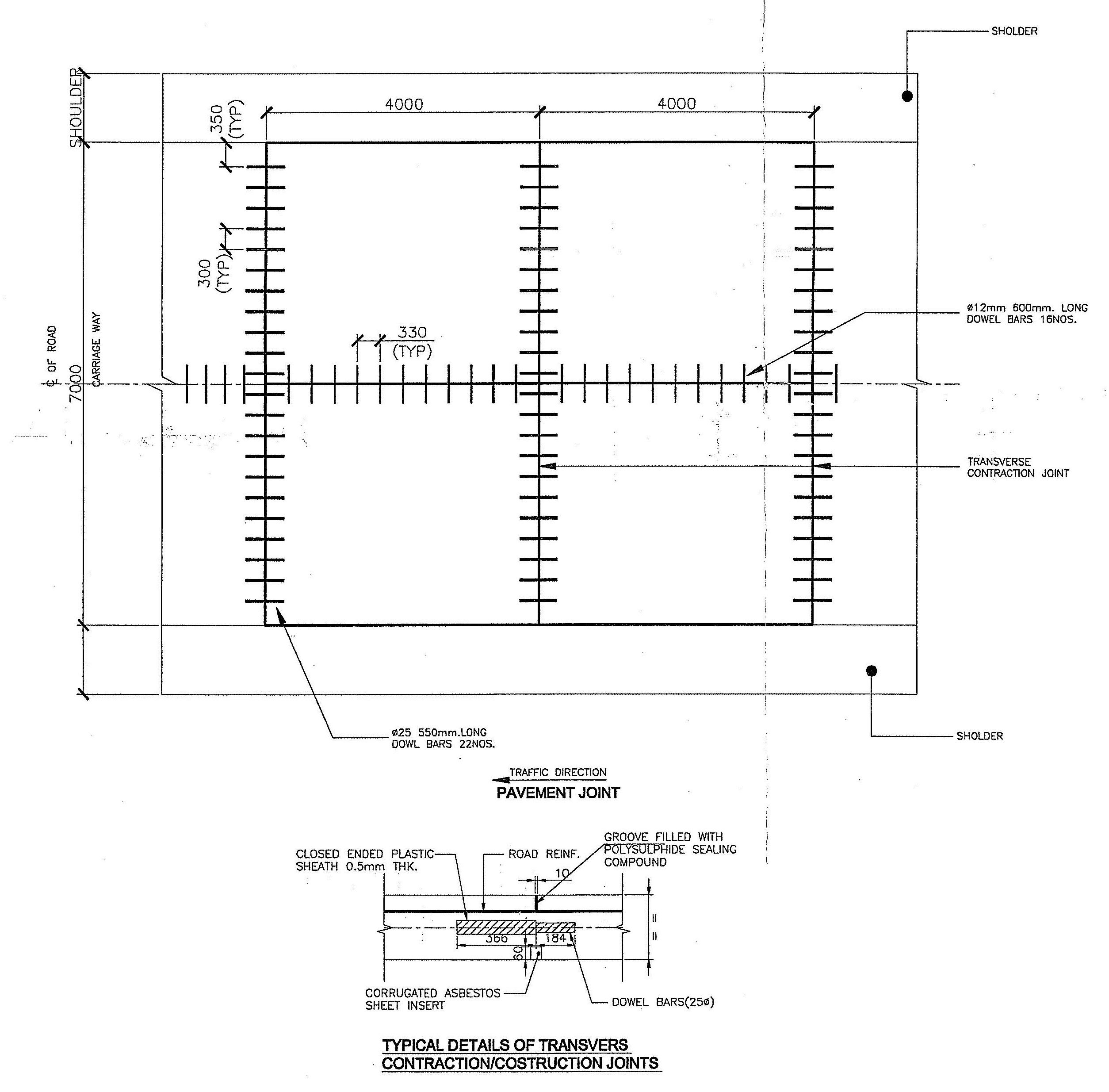
Typical Joint Layout for a 8 m Wide Road
The second drawing illustrates a wider roadway section.
Key Dimensions
| Parameter | Value |
|---|---|
| Road Width | 8.0 m |
| Transverse Joint Spacing | 4.0 m |
| Longitudinal Joint Dowel Spacing | 330 mm |
| Longitudinal Dowel Diameter | 12 mm |
| Longitudinal Dowel Length | 600 mm |
| Number of Longitudinal Dowels | 16 Nos |
For wider pavements, a longitudinal joint is introduced at the centerline to divide the slab and control longitudinal cracking.
Expansion Joint Details
Purpose of Expansion Joints
Expansion joints allow the concrete slabs to expand during high temperatures without generating excessive compressive stress.
Without expansion joints:
- Slab buckling may occur.
- Blow-ups can develop.
- Edge spalling may increase.
- Pavement service life decreases.


Components of the Expansion Joint
The drawing identifies the following components:
1. Dowel Bars (25 mm Diameter)
- Diameter: 25 mm
- Length: 550 mm
- Positioned at mid-depth of slab
- Facilitate load transfer between adjacent slabs
- Permit horizontal movement
2. Plastic Sheath
One end of the dowel bar is enclosed in:
- Closed-ended plastic sheath
- Thickness: 0.5 mm
This allows the dowel bar to slide freely when the slab expands or contracts.
3. Compressible Filler Board
The gap between slabs contains a compressible filler material that:
- Absorbs expansion movement
- Prevents concrete-to-concrete contact
- Reduces compressive stress buildup
4. Debonding Strip
A debonding strip of approximately 1–2 mm thickness is provided beneath the sealant to prevent adhesion at the base of the sealant reservoir.
5. Sealant
The top groove is sealed using:
- Polysulphide sealant
- Silicone sealant
Functions:
- Prevents water infiltration
- Stops debris entry
- Protects underlying filler material
Detail “C” – Expansion Joint Section
The section labeled Detail “C” shows:
Dimensions
- Joint opening: approximately 20 mm
- Sealant depth: 25 mm
- Pavement thickness: 225 mm
Layer Arrangement
From top to bottom:
- Polysulphide/Silicone Sealant
- Debonding Strip
- Compressible Filler Board
- Dowel Bars
- Concrete Slab
This arrangement allows movement while maintaining load transfer capability.
Transverse Contraction Joint Details
Purpose
Concrete shrinks during curing and temperature reduction. Contraction joints create predetermined weak planes where controlled cracking can occur.
Benefits include:
- Prevention of random cracking
- Improved riding quality
- Better load transfer
- Enhanced durability
Joint Spacing
According to the drawing:
- Joint spacing = 4.0 meters c/c
This spacing minimizes tensile stress due to shrinkage.
Construction Features
The transverse contraction joint includes:
Dowel Bars
- Diameter: 25 mm
- Length: 550 mm
These transfer wheel loads from one slab to the next.
Groove Formation
A groove is formed at the pavement surface and filled with:
- Polysulphide sealing compound
Corrugated Insert
The drawing indicates a corrugated insert beneath the groove, helping create a controlled cracking plane.
Load Transfer Mechanism
When a vehicle wheel passes over a joint:
- One slab tends to deflect.
- Dowel bars transfer part of the load to the adjacent slab.
- Differential settlement is reduced.
- Joint faulting is minimized.
Proper dowel alignment is essential for effective load transfer.
Longitudinal Joint Details
Purpose
Longitudinal joints are provided in wider pavements to:
- Control longitudinal cracking
- Divide wide slabs into manageable widths
- Improve structural performance
The drawing shows a longitudinal joint positioned along the pavement centerline.
Components of Longitudinal Joint
Tie Bars
The drawing specifies:
- 12 mm diameter tie bars
- 600 mm length
- Spaced approximately 330 mm center-to-center
These bars:
- Hold adjacent slabs together
- Prevent joint opening
- Do not permit movement like dowel bars
Separation Membrane
A separation membrane is provided beneath the joint area to assist in crack control and reduce friction effects.
Groove Sealant
The groove is sealed using:
- Polysulphide sealant
- Silicone sealant
This prevents ingress of:
- Water
- Dust
- Incompressible materials
Detail “B” – Longitudinal Joint Section
Groove Characteristics
The drawing indicates:
- Initial groove width: 3–4 mm
- Widened groove at top
- Sealant depth: 15 mm
- Groove width at top: 6–8 mm
Additional Components
- Soft backing rod
- Debonding strip
- Sealant reservoir
This configuration ensures proper sealant performance and flexibility.
Reinforcement Details
The reinforcement layout shown in the drawing provides:
Dowel Bar Arrangement
For Transverse Joints:
- Ø25 mm × 550 mm long
- Approximately 300 mm spacing
For Longitudinal Joints:
- Ø12 mm × 600 mm long
- Approximately 330 mm spacing
Reinforcement Benefits
- Better load transfer
- Reduced edge stresses
- Controlled crack propagation
- Increased pavement life
Importance of Joint Sealing
Joint sealing is a critical maintenance and durability requirement.
Proper sealing prevents:
Water Infiltration
Water entering joints can cause:
- Subgrade weakening
- Pumping action
- Erosion of support layers
Debris Intrusion
Incompressible materials entering joints can create:
- High expansion pressure
- Edge spalling
- Slab cracking
Reinforcement Corrosion
Effective sealing protects steel components from moisture and chlorides.
Construction Recommendations
For successful pavement performance:
During Construction
- Ensure accurate dowel alignment.
- Maintain specified joint spacing.
- Install tie bars correctly.
- Use approved sealant materials.
- Keep joints clean before sealing.
During Maintenance
- Inspect joints periodically.
- Replace damaged sealant.
- Repair spalled edges promptly.
- Monitor joint movement.
Advantages of Proper Joint Design
A well-designed joint system provides:
✔ Controlled cracking
✔ Smooth riding surface
✔ Effective load transfer
✔ Reduced maintenance costs
✔ Longer pavement life
✔ Better structural performance
✔ Improved water resistance
✔ Enhanced durability under traffic loads
Conclusion
The pavement joint details shown in the drawings represent a standard rigid pavement design incorporating expansion joints, transverse contraction joints, and longitudinal joints. Expansion joints accommodate thermal movement, contraction joints control shrinkage cracking, and longitudinal joints stabilize wider pavements. Together with properly installed dowel bars, tie bars, sealants, and filler materials, these joints ensure long-term pavement performance, structural integrity, and riding comfort.
Rate This Blog
Total Ratings: 0
For road construction projects, strict adherence to these joint details is essential to maximize pavement service life and minimize future maintenance requirements.
- Expansion Joints in Concrete Pavements
 Concrete pavements are designed to withstand heavy traffic loads, temperature… Read more: Expansion Joints in Concrete Pavements
 - RCC Staircase Detail Drawing free pdf Download
 Reinforced Cement Concrete (RCC) staircases are one of the most… Read more: RCC Staircase Detail Drawing free pdf Download
 - Pipe Rack GA Drawing Layout
 Image – Typical Pipe Rack GA Drawing Explanation The above… Read more: Pipe Rack GA Drawing Layout
 - Bund Wall Detail Drawing for Tank Farm and Oil Storage Area
 Introduction A bund wall (also called a dyke wall or… Read more: Bund Wall Detail Drawing for Tank Farm and Oil Storage Area
 - Dyke Wall Layout and Detail | Oil Tank Containment Systems |
 Introduction A dyke wall (also called a bund wall or… Read more: Dyke Wall Layout and Detail | Oil Tank Containment Systems |
 - How to Assign LY and LZ in STAAD for Steel Structures (With and Without Bracing)
 🔹 What is LY and LZ? In STAAD.Pro: These define… Read more: How to Assign LY and LZ in STAAD for Steel Structures (With and Without Bracing)
 - EDG Building Power Cable Layout with MTO Guide
 Introduction An Emergency Diesel Generator (EDG) system is a critical… Read more: EDG Building Power Cable Layout with MTO Guide
 - Septic Tank Drawing and Details
 Septic tanks are widely used in residential buildings for on-site… Read more: Septic Tank Drawing and Details
 - Holding Tank Detail
 Introduction A holding tank, also known as a water sump… Read more: Holding Tank Detail
 - Rain Water Harvesting System pdf Book Download
 TABLE OF CONTENTS 1.0 INTRODUCTION 3 2.0 CHAPTER 1 4… Read more: Rain Water Harvesting System pdf Book Download
 - Galvanized Gate | Design Details and Specifications Guide |
 Introduction Industrial galvanized gates are designed for heavy-duty usage, high… Read more: Galvanized Gate | Design Details and Specifications Guide |
 - Soak Pit Details | Seepage Pit |
 Introduction A soak pit or seepage pit (also called a… Read more: Soak Pit Details | Seepage Pit |
 - Expansion, Contraction and Construction Joints in Concrete for Civil Works
 1. Introduction Concrete is one of the most widely used… Read more: Expansion, Contraction and Construction Joints in Concrete for Civil Works
 - Cable Rack Structural Steel Detail and Design
 Introduction Cable racks (also called cable trays or cable support… Read more: Cable Rack Structural Steel Detail and Design
 - RCC Shear Wall Details
 Introduction Reinforced Cement Concrete (RCC) shear walls are one of… Read more: RCC Shear Wall Details
 - RCC Column with Splice and Coupler in Reinforcement Free Download
 Introduction Reinforced Cement Concrete (RCC) columns are one of the… Read more: RCC Column with Splice and Coupler in Reinforcement Free Download
 - Manhole Types and Details
 Manholes are essential underground structures used in sewer systems, stormwater… Read more: Manhole Types and Details
 - Catch Basin Types and Details
 Catch basins are essential components of stormwater management systems. They… Read more: Catch Basin Types and Details
 - Foundation Detail Drawings for Buildings With CAD Files
 A Practical Structural Drawing Guide Introduction Footing drawings form the… Read more: Foundation Detail Drawings for Buildings With CAD Files
 - Bar Bending Schedule | BBS Calculator For Beam Column and Slab
 Managing the Bar Bending Schedule (BBS) is one of the… Read more: Bar Bending Schedule | BBS Calculator For Beam Column and Slab
 - Room Paint Calculator | Paint, Primer & Putty Quantity & Cost Estimator
 Looking to renovate your room? Our Room Paint, Primer &… Read more: Room Paint Calculator | Paint, Primer & Putty Quantity & Cost Estimator
 - Brick Wall Construction Calculator | Calculate Bricks & Cost Instantly |
 Introduction Building a brick wall requires accurate planning to avoid… Read more: Brick Wall Construction Calculator | Calculate Bricks & Cost Instantly |
 - Unit Converter – Feet, Inches, cm, mm, Yard to Meter and Vice Versa
 Length Unit Converter 🌙 Toggle Dark Mode Length Unit Converter… Read more: Unit Converter – Feet, Inches, cm, mm, Yard to Meter and Vice Versa
 - Civil Engineering Interview Questions and Important Practical Foundation
 1. What factors affect the selection of foundation type? Soil… Read more: Civil Engineering Interview Questions and Important Practical Foundation
 - Road Turning Radius as per IS/IRC Codes and International Standards AASHTO BS/DMRB
 1. Turning Radius as per Indian Standards (IRC/IS Codes) In… Read more: Road Turning Radius as per IS/IRC Codes and International Standards AASHTO BS/DMRB
Leave a Reply