
A test pile is installed to verify the load-bearing capacity, settlement behaviour, and structural integrity of foundation piles before full-scale construction. Test piles help ensure safe and economical pile foundation design.
1. Purpose of Test Pile Design
✔ Verify Pile Load Capacity – Ensures piles can support design loads.
✔ Determine Settlement Characteristics – Helps in evaluating soil behaviour under loading.
✔ Assess Construction Feasibility – Confirms installation techniques and soil interactions.
✔ Optimize Pile Design – Reduces unnecessary conservatism in pile dimensions.
2. Types of Pile Load Tests
| Test Type | Purpose | Load Application |
| Static Load Test | Determines ultimate bearing capacity | Axial compression, tension, or lateral load |
| Dynamic Load Test | Measures resistance via hammer impact | Drop-weight hammer (PDA test) |
| Integrity Test | Checks defects and continuity | Sonic echo or crosshole sonic logging |
| Lateral Load Test | Assesses horizontal pile resistance | Lateral force applied at pile head |


3. Design Parameters for Test Pile
✔ Pile Type: Bored Cast-in-Situ, Driven Pile, Micro Pile, or Steel Pile
✔ Pile Diameter (D): Typically 300mm – 1200mm for cast-in-situ piles
✔ Pile Length (L): Based on soil profile, typically 10m – 50m
✔ Safe Load (Qsafe): Determined from soil investigation report
✔ Factor of Safety (FOS): Typically 2.5 – 3.0
4. Test Pile Load Calculation
The Ultimate Load Capacity (Qult) of a pile is given by:
Qult=Qs+Qp
Where:
- Qs = Skin Friction Resistance
- Qp = End Bearing Resistance
a. Skin Friction Resistance (Q_s)
Qs=∑fs×As
Where:
- fs = Skin friction per unit area (kN/m²)
- As = Surface area of the pile in contact with soil
b. End Bearing Resistance (Qp)
Qp = qp×Ap
Where:
- qp = End bearing capacity (kN/m²)
- Ap = Pile tip cross-sectional area
c. Safe Load Capacity
Qsafe=Qult / FOS
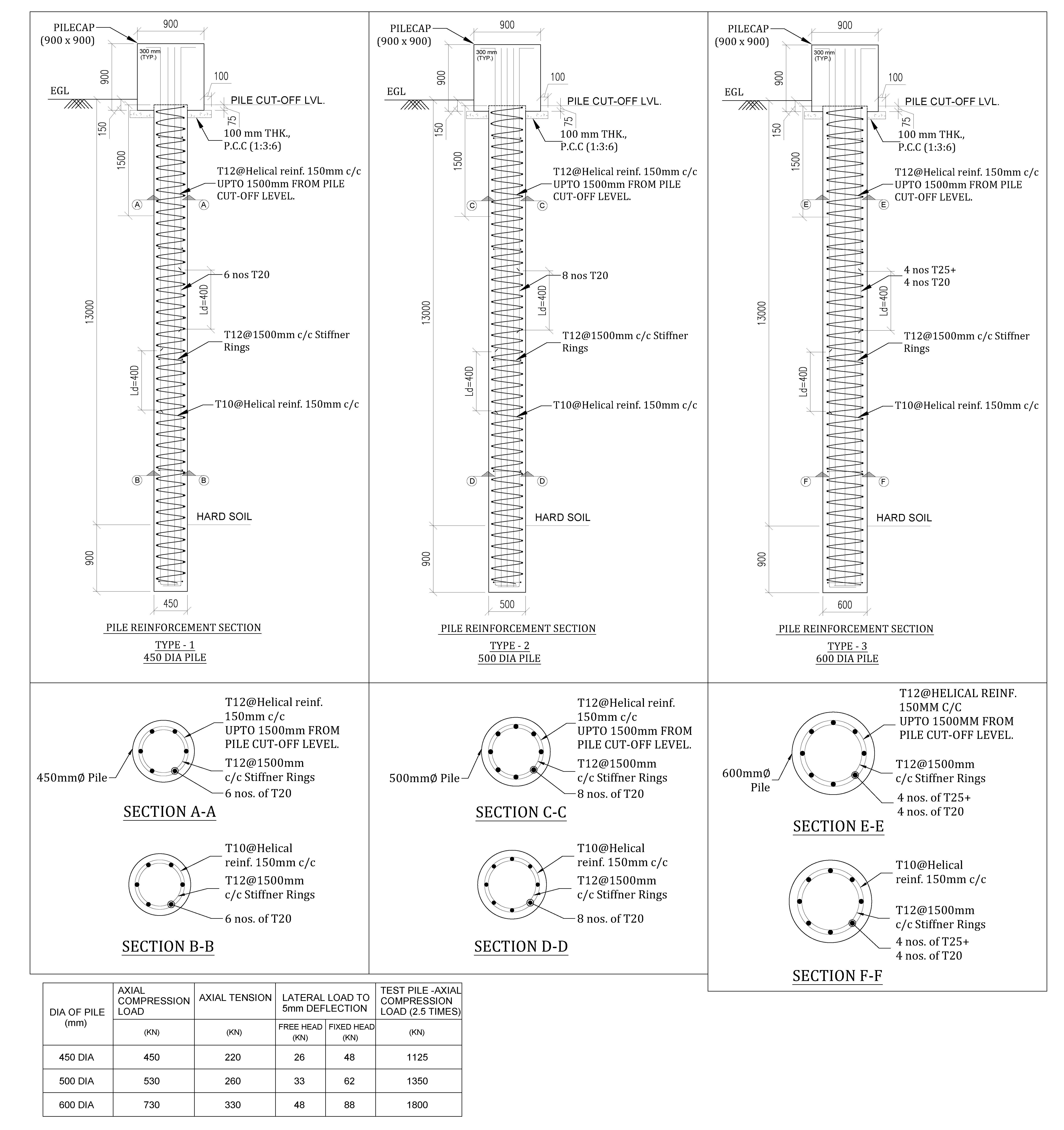
✔ Example Calculation: For a 600mm diameter pile with L = 25m
- Soil friction (fs) = 35 kN/m²
- End bearing (qp) = 3000 kN/m²
- FOS = 2.5
Qs = (35×π×0.6×25) =1648.5kN
Qp = (3000×π/4×0.62) =848.8kN
Qult = 1648.5+848.8 =2497.3kN
Qsafe = 2497.3 / 2.5 =998.9kN
Thus, the safe load-carrying capacity of the test pile is 999 kN.
5. Pile Load Test Setup & Procedure
✔ Test Pile Installation: Constructed in the same method as working piles.
✔ Load Application: Hydraulic jack with Kentledge system or anchor piles.
✔ Load Increments: Applied in steps of 25% of working load.
✔ Settlement Measurement: Recorded at each load stage.
✔ Test Duration: Maintained for 24–48 hours to observe settlement.
6. Acceptance Criteria for Test Pile
| Criterion | Limit Value |
| Total Settlement | ≤ 10% of pile diameter |
| Net Settlement after 24 hrs | ≤ 12 mm |
| Elastic Recovery | ≥ 80% of applied deflection |
| Ultimate Load (Q_ult) | At least 2.5 times working load |
7. Compliance with Standards & Codes
| Standard | Description |
| IS 2911: Part 4 | Load Test on Piles (Indian Code) |
| ASTM D1143 | Standard Test Methods for Axial Pile Load Test |
| BS 8004 | Foundation Design and Construction (UK) |
| ACI 543R | Guide for Pile Design in Concrete Structures |
8. Free Downloads – Pile Load Test Reports & Design Sheets
📥 Pile Load Test Report Template (PDF & Word)
📥 Excel Spreadsheet for Pile Load Calculation
📥 Pile Load Test Data Sheet (IS & ASTM Format)
📥 AutoCAD Drawing for Test Pile Setup
9. Conclusion
✔ Test piles are essential for verifying foundation strength and ensuring safety.
✔ Proper pile load calculation helps optimize design and cost.
✔ Field load testing ensures compliance with IS, ASTM, and BS codes.
💬 Need detailed test pile reports or AutoCAD drawings? Contact us for professional support! 🚀🏗️
- Eurocode Base Plate Calculator – EN 1993-1-8Introduction Base plates are critical components in steel structures, transferring… Read more: Eurocode Base Plate Calculator – EN 1993-1-8
- Base Plate Design Calculation AS 4100Introduction In structural steel design, the base plate is a… Read more: Base Plate Design Calculation AS 4100
- Base Plate Design Calculator CSA A23.3Introduction Steel column base plates transfer loads from the column… Read more: Base Plate Design Calculator CSA A23.3
- Base Plate Design Calculator ACI 318Introduction Designing a steel column base plate is a critical… Read more: Base Plate Design Calculator ACI 318
- Base Plate Design as per IS 800 2007Introduction (Anchor Bolts Outside & Inside Column Flange) Base plates… Read more: Base Plate Design as per IS 800 2007
- Bar Bending Schedule | BBS Calculator For Beam Column and SlabManaging the Bar Bending Schedule (BBS) is one of the… Read more: Bar Bending Schedule | BBS Calculator For Beam Column and Slab
- Room Paint Calculator | Paint, Primer & Putty Quantity & Cost EstimatorLooking to renovate your room? Our Room Paint, Primer &… Read more: Room Paint Calculator | Paint, Primer & Putty Quantity & Cost Estimator
- Load Conversion & Stress Calculator | kN to kg, ton, N, MPa OnlineLoad Conversion & Stress Calculator for Civil and Structural Engineers… Read more: Load Conversion & Stress Calculator | kN to kg, ton, N, MPa Online
- Water Tank Capacity Calculator – Feet & Meter Conversion (Litres & Gallons)Water Tank Capacity Calculator with Unit Conversion Accurate water storage… Read more: Water Tank Capacity Calculator – Feet & Meter Conversion (Litres & Gallons)
- Brick Wall Construction Calculator | Calculate Bricks & Cost Instantly |Introduction Building a brick wall requires accurate planning to avoid… Read more: Brick Wall Construction Calculator | Calculate Bricks & Cost Instantly |
- Unit Converter – Feet, Inches, cm, mm, Yard to Meter and Vice VersaLength Unit Converter 🌙 Toggle Dark Mode Length Unit Converter… Read more: Unit Converter – Feet, Inches, cm, mm, Yard to Meter and Vice Versa
- Lifting Analysis of Skid Using Spreader Beam 4-PointCOG Shift, Moment Calculation & Sling Forces for STAAD Pro… Read more: Lifting Analysis of Skid Using Spreader Beam 4-Point
- Base Plate Design as per IS Code | IS 800:2007 Steel Column Base |Introduction In steel structures, the base plate is a critical… Read more: Base Plate Design as per IS Code | IS 800:2007 Steel Column Base |
- Wind Load Calculation IS 875 Part 3 2015Below is a compact, practical guide you can use on… Read more: Wind Load Calculation IS 875 Part 3 2015
- Road Turning Radius as per IS/IRC Codes and International Standards AASHTO BS/DMRB1. Turning Radius as per Indian Standards (IRC/IS Codes) In… Read more: Road Turning Radius as per IS/IRC Codes and International Standards AASHTO BS/DMRB
- Foundation Design ACI 318 pdf & Excel DownloadIn ACI 318 (American Concrete Institute’s Building Code Requirements for… Read more: Foundation Design ACI 318 pdf & Excel Download
- Design of Steel Silo1. Introduction Steel silo is, typical uses (grain, cement, powders),… Read more: Design of Steel Silo
- Design of Beam to Beam End Plate ConnectionBeam end-to-end connections (splices) ensure continuity and safe transfer of… Read more: Design of Beam to Beam End Plate Connection
- DESIGN OF FLAT SLAB pdf Free Download🔹 What is a Flat Slab? A flat slab is… Read more: DESIGN OF FLAT SLAB pdf Free Download
- Design of Thrust BlockThrust blocks are one of the most important structural components… Read more: Design of Thrust Block
- DESIGN OF BARREL FOR BOX CULVERT pdf Free DownloadBox culvert design according to IRC 6 (Standard Specifications and Code… Read more: DESIGN OF BARREL FOR BOX CULVERT pdf Free Download
- Design of Retaining Wall Calculation pdf Free DownloadRetaining walls are essential structural elements in civil engineering, used… Read more: Design of Retaining Wall Calculation pdf Free Download
- Analysis and Design of Drain Sump PitIntroduction A sump pit, commonly used in buildings, industrial plants,… Read more: Analysis and Design of Drain Sump Pit
- Design of Steel Shelter as per IS 800Designing a steel shelter requires a clear understanding of structural… Read more: Design of Steel Shelter as per IS 800
- Octagonal Pedestal DesignDesigning an octagon pedestal as per ACI (American Concrete Institute)… Read more: Octagonal Pedestal Design
- Ring Wall Foundation Design✅ Overview A Ring Wall Foundation is a circular or… Read more: Ring Wall Foundation Design
- Decking Sheet with Concrete – Design Details & SpecificationsOverview Decking sheets, also known as composite metal decks or… Read more: Decking Sheet with Concrete – Design Details & Specifications
- Hydrodynamic Load on Tanks | Convective and Impulsive |Hydrodynamic loads for tanks refer to the forces exerted on… Read more: Hydrodynamic Load on Tanks | Convective and Impulsive |
- PILE STIFFNESS CALCULATIONSTAAD INPUT FOR SUPPORT CONDITION VERTICAL STIFFNESSAllowable vertical settlement =… Read more: PILE STIFFNESS CALCULATION
- Concrete Beam Design ACI 318Concrete beams are essential structural components in reinforced concrete construction,… Read more: Concrete Beam Design ACI 318
- Floor Slab Design One Way as per ACI 318One-way slabs are one of the most commonly used structural… Read more: Floor Slab Design One Way as per ACI 318
- Floor Slab Design Two way as per ACI 318Two-way floor slabs are the backbone of most modern reinforced… Read more: Floor Slab Design Two way as per ACI 318
- Loads and Load Combinations as per AS/NZS 1170.0 2002Designing Piperacks (pipe support structures) in compliance with Australian Standards… Read more: Loads and Load Combinations as per AS/NZS 1170.0 2002
- Design of Pump Foundation Dynamic and Static AnalysisDesign workflow (step-by-step) 2) Loads you must consider (typical) 3)… Read more: Design of Pump Foundation Dynamic and Static Analysis
- Stormwater Drainage CalculationDesigning 🌧️ Stormwater Drainage systems is essential to ensure the… Read more: Stormwater Drainage Calculation
- Structural Engineering Design Criteria – American Codes and StandardsIn the United States, structural engineering design is governed by… Read more: Structural Engineering Design Criteria – American Codes and Standards
- Anchor Bolts Length as per ACI 318-14In ACI 318-14 (“Building Code Requirements for Structural Concrete”), the… Read more: Anchor Bolts Length as per ACI 318-14
- Wind Load Calculations ASCE 7-16 Pdf Free DownloadWind Speed Calculation as per ASCE 7-16 (“Minimum Design Loads… Read more: Wind Load Calculations ASCE 7-16 Pdf Free Download
- Test Pile Drawing Calculation & GuidelinesA test pile is installed to verify the load-bearing capacity,… Read more: Test Pile Drawing Calculation & Guidelines
- Wind Load Calculation as per Australian Code (AS/NZS 1170.2:2021)Wind loads in Australia are calculated based on AS/NZS 1170.2:2021… Read more: Wind Load Calculation as per Australian Code (AS/NZS 1170.2:2021)
- Standard Road DetailsRigid & Flexible Road Details – Drawings & Requirements Road… Read more: Standard Road Details
- SHEAR FORCE AND BENDING MOMENT DIAGRAMS WITH FORMULAIntroduction Figures 1 through 32 provides a series of shear… Read more: SHEAR FORCE AND BENDING MOMENT DIAGRAMS WITH FORMULA
- Canadian Code Seismic Calculation ExampleThe National Building Code of Canada (NBC) 2020 provides the… Read more: Canadian Code Seismic Calculation Example
- Design Calculation of Steel Shelter – AISC 360PURPOSE AND SCOPE The scope of this document is to… Read more: Design Calculation of Steel Shelter – AISC 360
- Vertical Vessel Foundation DesignVertical Vessel foundation design The design of a foundation for… Read more: Vertical Vessel Foundation Design
- Effective Length for RCC ColumnsIn STAAD.Pro, ELY and ELZ are parameters used to define… Read more: Effective Length for RCC Columns
- DESIGN OF SLABS AS PER IS456DESIGN OF SLABS AS PER IS456 1. GENERAL A slab… Read more: DESIGN OF SLABS AS PER IS456
- Design of Staircase Waist SlabDesign of Staircase Waist Slab A waist slab is the… Read more: Design of Staircase Waist Slab
- Monorail Beam DesignDesigning a monorail beam as per IS 800:2007 (General Construction… Read more: Monorail Beam Design
- Concrete Beam Design as per Canadian Code (CSA A23.3-19)Concrete Beam Design as per Canadian Code (CSA A23.3-19) The… Read more: Concrete Beam Design as per Canadian Code (CSA A23.3-19)
- Wind Load Calculation as per Canadian Code | NBCC 2020 |To calculate wind load as per the National Building Code… Read more: Wind Load Calculation as per Canadian Code | NBCC 2020 |
- Transformer Foundation DesignDesigning a transformer foundation involves considering the transformer’s size, weight,… Read more: Transformer Foundation Design
- Box Culvert DesignBox culvert design according to IRC 6 (Standard Specifications and… Read more: Box Culvert Design
- Design of Anchor Reinforcement in Concrete PedestalsDesign of Anchor Reinforcement in Concrete Pedestals Pedestal rebars parallel… Read more: Design of Anchor Reinforcement in Concrete Pedestals
- Wind Load Calculation for Pipe RackTo calculate wind load on Pipe racks, open structures, cable trays… Read more: Wind Load Calculation for Pipe Rack
- Wind Load Calculation as Per Indian CodeWind Load Calculation Wind speed -33m/sec From Ground floor to… Read more: Wind Load Calculation as Per Indian Code
- Response Spectrum Analysis in STAAD proIn STAAD.Pro, combining loads using the SRSS (Square Root of… Read more: Response Spectrum Analysis in STAAD pro
- Side Face Reinforcement as per ACI & IS codeSide face reinforcement – IS 456:2000 (Indian Standard) The side… Read more: Side Face Reinforcement as per ACI & IS code
- Lifting Padeye DesignPadeye is a plate or attachment point commonly used in… Read more: Lifting Padeye Design
- Corbel Design and DetailsDESIGN OF CORBEL A corbel is a short cantilever used… Read more: Corbel Design and Details
- DYNAMIC ANALYSIS USING RESPONSE SPECTRUM ANALYSISThe purpose of this chapter is to summarize the fundamental… Read more: DYNAMIC ANALYSIS USING RESPONSE SPECTRUM ANALYSIS
- Building Load Calculation1. INTRODUCTION: The structure is a “Multi-storied building” consisting of… Read more: Building Load Calculation
- Deep ExcavationsABSTRACT All major topics in the design of in-situ… Read more: Deep Excavations
- Structural Design of working pileDesigning working piles according to IS 2911 (Part 1 to… Read more: Structural Design of working pile
- Design of Gantry GirderDesigning a crane girder, which is a key structural component… Read more: Design of Gantry Girder
- Seismic Load Calculation as per ASCE 7-16The summary of the process to calculate the Design Spectral Acceleration at Short Periods (SDS) as per AISC 07-16 involves five steps: determining the site class, obtaining mapped spectral acceleration values, determining site coefficients (Fa and Fv), calculating adjusted spectral accelerations, and lastly, calculating the design spectral values (SDS and SD1). These values ensure structures can withstand anticipated earthquake forces.
- DESIGN OF WIND PRESSURE AS PER EN 1991-1-4The calculation for wind load as per EN 1991-1-4 for a gas plant located in a terrain category I includes parameters such as a fundamental basic wind velocity of 32.30 m/s, a directional factor and season factor of 1.00 each, and various terrain factors and roughness lengths. Wind turbulence intensity and peak velocity pressure vary with height.
- Trench DetailsDesigning a reinforced concrete (RCC) trench involves several steps to… Read more: Trench Details
- PRECAST COVER SLAB DETAILSDesigning a precast cover slab for a trench involves ensuring… Read more: PRECAST COVER SLAB DETAILS
- Grade Slab DetailsPaving or Grade slab Details A grade slab, also known… Read more: Grade Slab Details
- CONCRETE BATCHING PLANT ARRANGEMENTA well-designed batching plant arrangement ensures efficient concrete production, safety,… Read more: CONCRETE BATCHING PLANT ARRANGEMENT
- LOAD COMBINATIONS NBCC 2023LOAD COMBINATIONS CANADIAN CODE NBCC 2023 The National Building Code… Read more: LOAD COMBINATIONS NBCC 2023
- STEEL SHED DRAWING1. Plan View (Top View): Outline of the Shed: Show… Read more: STEEL SHED DRAWING
- Plumbing DrawingCreating a plumbing scheme drawing involves outlining the entire plumbing… Read more: Plumbing Drawing
- Pre Engineered Building Design Specification IS CodePre-Engineered Building PEB PEB stands for Pre-Engineered Building. It refers… Read more: Pre Engineered Building Design Specification IS Code
- DESIGN OF PIPERACK STRUCTUREDESIGN OF PIPERACK STRUCTURE – ASCE 7-10 The length of… Read more: DESIGN OF PIPERACK STRUCTURE