
MARRIAGE HALL PLAN SOUTH FACING
Marriage Hall plan layouts with Ground + 3 floors, the floors are completely utilized without wastage of floor. The plot size is 41 feet x 85 feet and plinth area of building is 33 feet x 77 feet. The plan area of marriage hall is 2541 sqft with fully occupied floor place. Parking at ground, first and second floor, utilities, lift, staircase, and well accommodating floor space. 200 Nos seating capacity, stage and music stage arrangement in hall. Dining area is 1650sqft at first floor and 10 Nos of room at the third floor location.
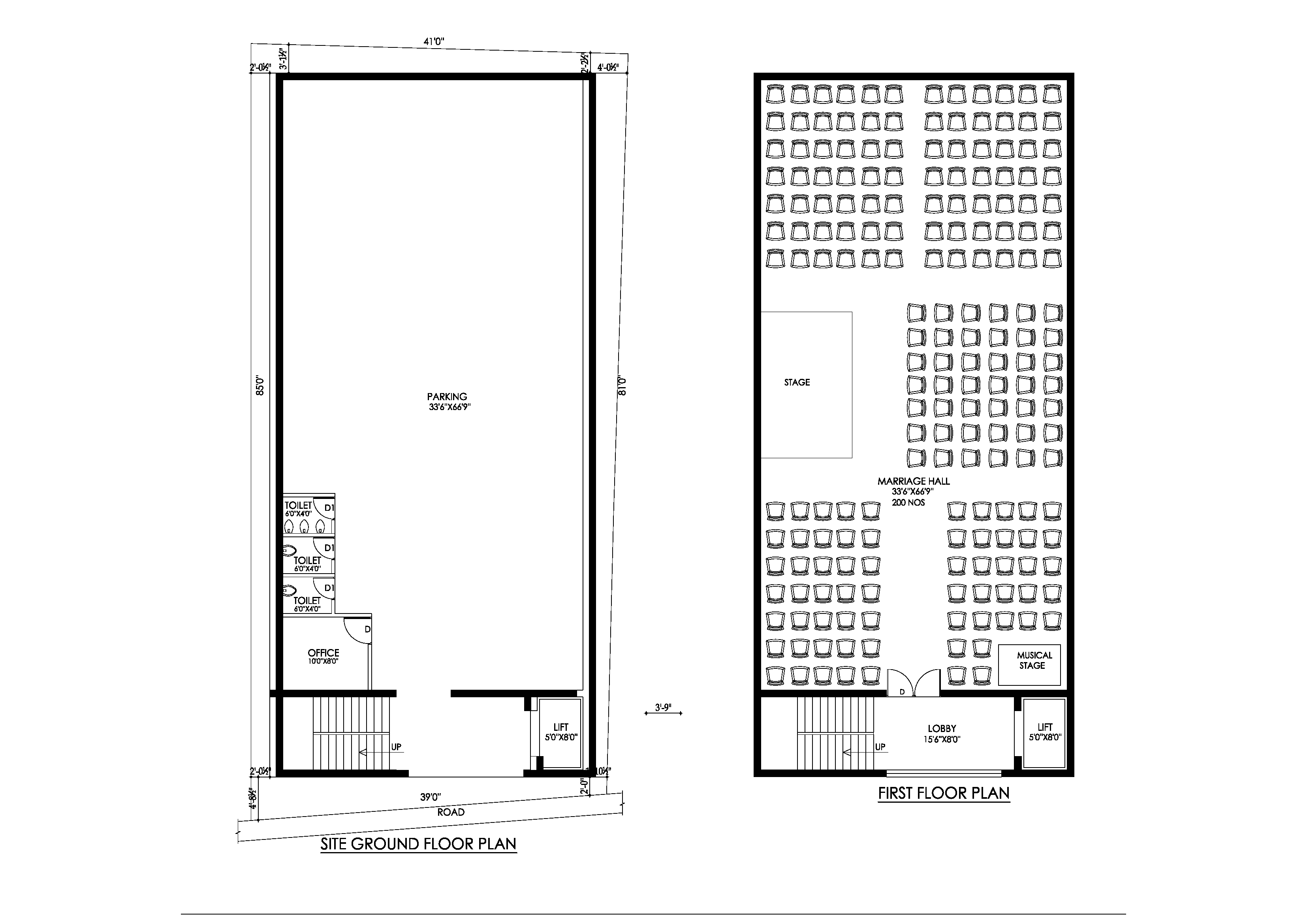
It’s an architectural marriage hall plan with parking and stage and dinning with full marked dimensions
Available column location scheme drawing and beam layout for further ready to construction reference.
Commercial Building Plans with Dimensions AutoCAD file; download commercial building layout plan with dimension detail in DWG format.
Open and edit any plan to make it your own.
Marriage Hall Plan
- PARKING 33’6”X66’9”
- MARRIAGE HALL 33’6”X66’9” 200 NOS OF SEATING CAPACITY
- HALL AREA -2 AT FIRST FLOOR – 540 SQFT
- DINING 33’6”X50’0”
- ROOMS 10NOS
- LIFT
Ground Floor and First Floor Plan of Marriage Hall

Categories
- 3D HOUSE DESIGN (34)
- Civil and Structural Design Calculations (76)
- Commercial Plans (9)
- East Facing House Plans (14)
- Engineering Concepts – Civil & Structural (224)
- Excel Spreadsheets (37)
- Free Downloads (49)
- House Plans (57)
- Industrial standards (91)
- North Facing House Plans (15)
- South Facing House Plans (15)
- West Facing House Plans (9)
Second Floor and Third Floor Plan of Marriage Hall

Recent Posts
- Catch Basin Types and Details
- Eurocode Base Plate Calculator – EN 1993-1-8
- Base Plate Design Calculation AS 4100
- Base Plate Design Calculator CSA A23.3
- Base Plate Design Calculator ACI 318
- Base Plate Design as per IS 800 2007
- East Facing 38×56 House Plan – Ground & First Floor Design with 3BHK + Home Theatre
- Foundation Detail Drawings for Buildings With CAD Files
- Bar Bending Schedule | BBS Calculator For Beam Column and Slab
- Room Paint Calculator | Paint, Primer & Putty Quantity & Cost Estimator
- Load Conversion & Stress Calculator | kN to kg, ton, N, MPa Online
- Water Tank Capacity Calculator – Feet & Meter Conversion (Litres & Gallons)
- Brick Wall Construction Calculator | Calculate Bricks & Cost Instantly |
- Unit Converter – Feet, Inches, cm, mm, Yard to Meter and Vice Versa
- Lifting Analysis of Skid Using Spreader Beam 4-Point
- Base Plate Design as per IS Code | IS 800:2007 Steel Column Base |
- Laser Cut Railing Price in India 2025 | MS & SS CNC Balcony Designs
- MS Balcony Railing Price in India 2026 | Mild Steel Railing Works |
- Stainless Steel with Glass Handrail Price 2026
- Modern Duplex House West Facing 36 x 48
- Pooja Room Door Design
- Modern House 3D Design – Visualizing Your Dream Home
- Balcony Railing Designs for Modern Homes
- Civil Engineering Interview Questions and Important Practical Foundation
- Wind Load Calculation IS 875 Part 3 2015
- Front Elevation Design for Modern Homes
- Road Turning Radius as per IS/IRC Codes and International Standards AASHTO BS/DMRB
- Foundation Design ACI 318 pdf & Excel Download
- Steel Staircase Design
- Front Elevation 20×60 House
- Steel Shed with Mezzanine Floor
- Structural Masonry Designers Manual
- Water Supply Piping Plan and Plumbing Schematic Diagram
- Sump Pit Drawing
- Design of Steel Silo
- Design of Beam to Beam End Plate Connection
- DESIGN OF FLAT SLAB pdf Free Download
- Design of Thrust Block
- Cage Ladder Detail Standard Drawing pdf Free Download
- DESIGN OF BARREL FOR BOX CULVERT pdf Free Download
- Design of Retaining Wall Calculation pdf Free Download
- Analysis and Design of Drain Sump Pit
- Design of High Rise Buildings as per Eurocode
- Design of Steel Shelter as per IS 800
- Octagonal Pedestal Design
- Ring Wall Foundation Design
- Decking Sheet with Concrete – Design Details & Specifications
- Hydrodynamic Load on Tanks | Convective and Impulsive |
- PILE STIFFNESS CALCULATION
- HOUSE PLAN 30 X 60 | SOUTH FACING |
- Concrete Beam Design ACI 318
- Floor Slab Design One Way as per ACI 318
- Floor Slab Design Two way as per ACI 318
- Ceiling Lights and Fan Layout Details
- Floor Tile Design Ideas
- Modern Boundary walls
- Lintel Slab Layout Details
- PILE CAP Detail Drawing
- Eurocode Load Combinations EN 1990 2002
- Expansion Joint Detail and Specification
- Storm Water Drain Detail Drawing
- Thrust Blocks and Restraints Details
- HOUSE PLAN 40 X 50 | SOUTH FACING |
- Octagonal Foundation Reinforcement Details
- Loads and Load Combinations as per AS/NZS 1170.0 2002
- Design of Pump Foundation Dynamic and Static Analysis
- HOUSE PLAN 60 X 40 | WEST FACING |
- Latest Staircase Handrail Design Ideas 40+
- HOUSE PLAN 50 X 50 | SOUTH FACING |
- Electrical Layout For Residential Building
- HOUSE PLAN 29 X 56 | SOUTH FACING |
- Rain Water Gutter and Down Take Systems
- Stormwater Drainage Calculation
- Structural Engineering Design Criteria – American Codes and Standards
- Anchor Bolts Length as per ACI 318-14
- Insert Plate Details & Drawing – Embedded in Concrete Structures
- JOURNAL PAPER GUIDELINES FOR ACSE
- Anchor Bolt Details and Drawing – Embedded in Concrete
- Staircase Layout and Details
- Guard House Layout and Details
- Pump Shed Structural Steel Drawing
- Wind Load Calculations ASCE 7-16 Pdf Free Download
- Column Buckling
- Moody Chart | Moment Reactions for Rectangular Plates |
- Test Pile Drawing Calculation & Guidelines
- Commercial Shop Plan
- Shop Floor Plan
- HOUSE PLAN WITH SHOP 40 x 60 | SOUTH FACING |
- Wind Load Calculation as per Australian Code (AS/NZS 1170.2:2021)
- HOUSE PLAN 30 X 45 | EAST FACING | INTERIOR HOUSE DESIGN |
- HOUSE PLAN 60 x 40 | EAST FACING | APARTMENT TYPE |
- Standard Road Details
- DG Building Architectural Plan & Finishing Schedule
- AMAZING TV UNIT IDEAS 90+ MODELS
- HOUSE PLAN 60 x 50 | EAST FACING |
- Technical Details for Wash Basin Section and Elevation
- Tender Technical Specification for Plumbing and Sanitary works
- HOUSE PLAN 25 x 50 | SOUTH FACING |
- HOUSE PLAN 60 x 45 | SOUTH FACING |
- Fencing Gate Details and Requirements