
Designing Piperacks (pipe support structures) in compliance with Australian Standards involves determining appropriate loads and load combinations. These ensure structural safety and serviceability under expected operating conditions.
📘 Relevant Australian Standards
- AS/NZS 1170 series – Structural design actions:
- AS/NZS 1170.0 – General principles
- AS/NZS 1170.1 – Dead and live loads
- AS/NZS 1170.2 – Wind actions
- AS/NZS 1170.4 – Earthquake actions
- AS 4100 – Steel structures (for structural design)
- AS 3990 – Mechanical equipment (can also be relevant)
- Client/project-specific specs may also impose extra load combinations.
🔩 Typical Loads on Piperacks
1. Dead Load (G)
- Self-weight of the steel structure.
- Weight of empty pipes, cable trays, and other permanent components.
- Pipe insulation or cladding if applicable.
2. Live Load (Q)
- Maintenance access (personnel loads).
- Temporary equipment.
- Occasional loads (e.g., pipe replacement).
3. Pipe Contents Load (Fluid Load)
- Internal fluid weight.
- May be treated as a variable action depending on operation.
4. Thermal Loads
- Axial expansion/contraction of pipes.
- Induces force on pipe supports if restrained.
5. Wind Load (W)
- As per AS/NZS 1170.2.
- Acts on structure and exposed surfaces (pipes, trays, etc.)
6. Seismic Load (E)
- As per AS/NZS 1170.4, especially in seismic-prone zones.
7. Equipment Loads
- Point loads or distributed loads from mounted equipment (valves, actuators).
8. Imposed Deformations
- Settlement or differential movement.
- Movement of connected equipment.
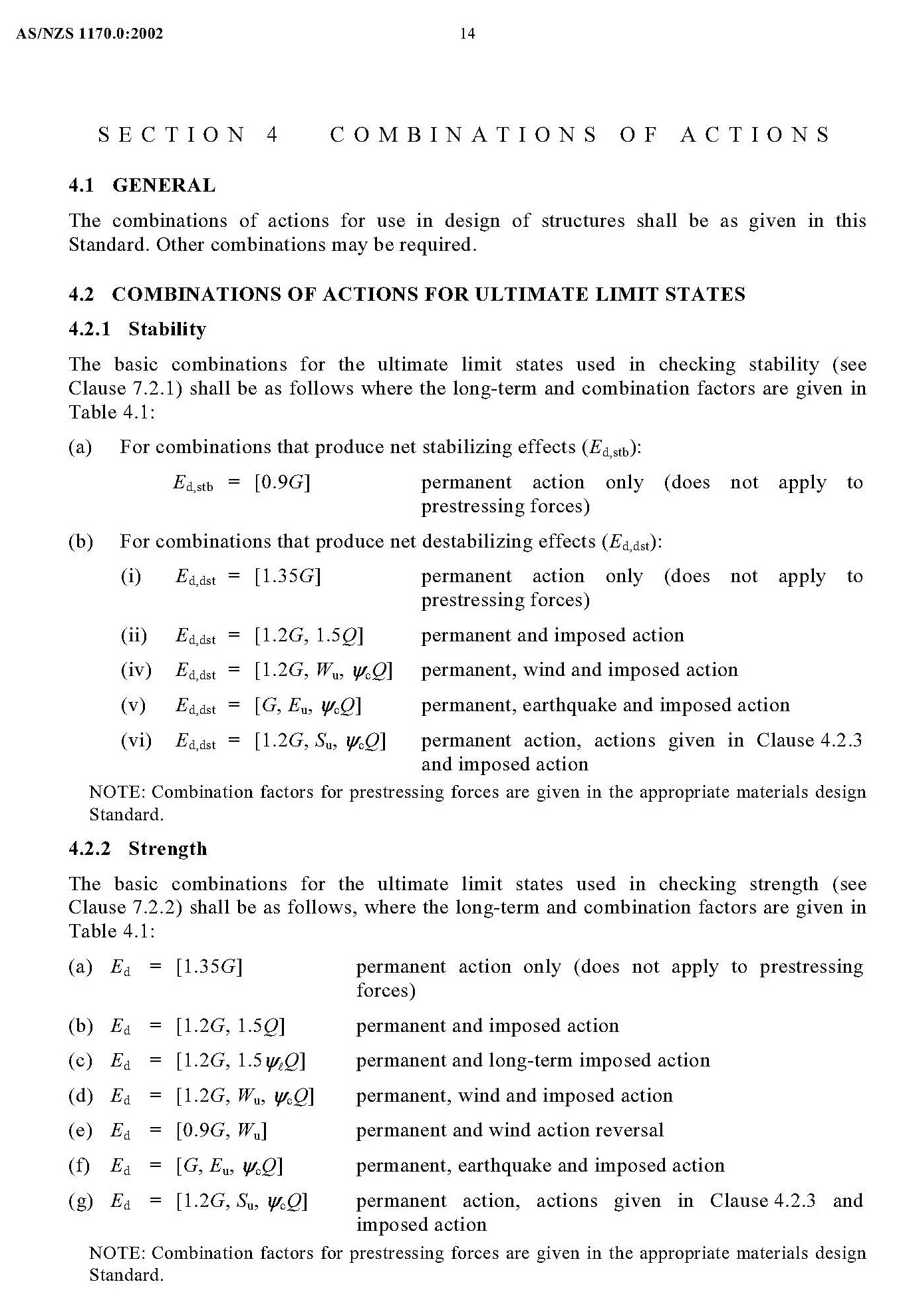
⚖️ Load Combinations (AS/NZS 1170.0:2002, Clause 4.2.1)
Ultimate Limit State (ULS)
Example combinations:
- G + Q
- G + Ψ<sub>l</sub>·Q + W
- G + W
- G + E
- G + T (thermal) (if thermal loads induce significant restraint forces)
Note: Factors and Ψ values depend on reliability class and action variability.
Serviceability Limit State (SLS)
Example combinations:
- G + Q
- G + W
- G + E
- G + T (thermal movements affecting deflection/expansion joints)
✅ Example Ultimate Load Combination (from AS/NZS 1170.0)
For normal importance structure:
Comb 1 1.2G + 1.5Q + 0.9W
Comb 2 1.2G + 1.5W + 0.9Q
Comb 3 1.2G + 1.3E
Adjust the coefficients based on the reliability level (importance) of the piperack.
📌 Notes
- Check for load cases with empty vs. full pipe conditions.
- Consider thermal loads as primary actions when they govern.
- Pipe supports may be designed for restrained or unrestrained thermal expansion.
- For dynamic loads (e.g., surge or vibration), specialized analysis is required.
General ULS Combination Format (Clause 4.2.1)
For permanent actions (G), variable actions (Q), and exceptional actions (A):
✅ Design action effect =
∑[G] + ∑[ψi·Qi] + ∑[ψE·Ei] + ∑[ψA·Ai]
But for ultimate limit state, the standard gives this general format:
🔸 Most common ULS combinations:
For normal structural importance (Importance Level 2):
1.2G + 1.5Q
1.2G + 1.5W + ψl·Q
1.2G + 1.3E + ψl·Q
Let’s break them down.
🧱 Detailed ULS Load Combinations for Piperacks
| Combination | Load Case | Formula | Notes |
|---|---|---|---|
| 1 | Dead + Live | 1.2G + 1.5Q | Most basic combination. |
| 2 | Dead + Wind | 1.2G + 1.5W | Wind governs in open or elevated areas. |
| 3 | Dead + Wind + Live | 1.2G + 1.5W + 0.4Q | Live load has reduced factor when accompanying wind. |
| 4 | Dead + Live + Wind (reverse) | 0.9G + 1.5W + 0.4Q | Use 0.9G when wind could uplift or reduce gravity effects. |
| 5 | Dead + Seismic | 1.2G + 1.3E | For seismic zones (per AS/NZS 1170.4) |
| 6 | Dead + Seismic + Live | 1.2G + 1.3E + 0.4Q | Live loads reduced due to improbability of concurrent peak. |
| 7 | Dead + Thermal + Live | 1.2G + 1.5T + 0.4Q | Thermal expansion restrained by structure. |
| 8 | Accidental loads (if any) | G + A or as specified | e.g., explosion, vehicle impact — project-specific. |
📌 Notes on Load Factors (per AS/NZS 1170.0)
| Action | Symbol | ULS Factor | SLS Factor |
|---|---|---|---|
| Dead Load | G | 1.2 or 0.9 | 1.0 |
| Live Load | Q | 1.5 | 1.0 |
| Wind Load | W | 1.5 | 1.0 |
| Earthquake Load | E | 1.3 | 1.0 |
| Thermal Load | T | 1.5 (if treated as action) | 1.0 |
- Use 0.9G when dead load resists overturning or uplift.
- Use 0.4Q as a companion load when it’s unlikely to occur at the same time as wind/seismic.
💡 Piperack-Specific Considerations
- For tall piperacks or racks with large-diameter pipes, wind often governs.
- For hot process plants, thermal expansion may create significant axial loads and needs inclusion in design.
- If piperack supports pipes with large slug flow (e.g., multiphase lines), account for dynamic surge — typically treated as an accidental or transient action.

- Eurocode Base Plate Calculator – EN 1993-1-8
 Introduction Base plates are critical components in steel structures, transferring… Read more: Eurocode Base Plate Calculator – EN 1993-1-8
 - Base Plate Design Calculation AS 4100
 Introduction In structural steel design, the base plate is a… Read more: Base Plate Design Calculation AS 4100
 - Base Plate Design Calculator CSA A23.3
 Introduction Steel column base plates transfer loads from the column… Read more: Base Plate Design Calculator CSA A23.3
 - Base Plate Design Calculator ACI 318
 Introduction Designing a steel column base plate is a critical… Read more: Base Plate Design Calculator ACI 318
 - Base Plate Design as per IS 800 2007
 Introduction (Anchor Bolts Outside & Inside Column Flange) Base plates… Read more: Base Plate Design as per IS 800 2007
 - Bar Bending Schedule | BBS Calculator For Beam Column and Slab
 Managing the Bar Bending Schedule (BBS) is one of the… Read more: Bar Bending Schedule | BBS Calculator For Beam Column and Slab
 - Room Paint Calculator | Paint, Primer & Putty Quantity & Cost Estimator
 Looking to renovate your room? Our Room Paint, Primer &… Read more: Room Paint Calculator | Paint, Primer & Putty Quantity & Cost Estimator
 - Load Conversion & Stress Calculator | kN to kg, ton, N, MPa Online
 Load Conversion & Stress Calculator for Civil and Structural Engineers… Read more: Load Conversion & Stress Calculator | kN to kg, ton, N, MPa Online
 - Water Tank Capacity Calculator – Feet & Meter Conversion (Litres & Gallons)
 Water Tank Capacity Calculator with Unit Conversion Accurate water storage… Read more: Water Tank Capacity Calculator – Feet & Meter Conversion (Litres & Gallons)
 - Brick Wall Construction Calculator | Calculate Bricks & Cost Instantly |
 Introduction Building a brick wall requires accurate planning to avoid… Read more: Brick Wall Construction Calculator | Calculate Bricks & Cost Instantly |
 - Unit Converter – Feet, Inches, cm, mm, Yard to Meter and Vice Versa
 Length Unit Converter 🌙 Toggle Dark Mode Length Unit Converter… Read more: Unit Converter – Feet, Inches, cm, mm, Yard to Meter and Vice Versa
 - Lifting Analysis of Skid Using Spreader Beam 4-Point
 COG Shift, Moment Calculation & Sling Forces for STAAD Pro… Read more: Lifting Analysis of Skid Using Spreader Beam 4-Point
 - Base Plate Design as per IS Code | IS 800:2007 Steel Column Base |
 Introduction In steel structures, the base plate is a critical… Read more: Base Plate Design as per IS Code | IS 800:2007 Steel Column Base |
 - Wind Load Calculation IS 875 Part 3 2015
 Below is a compact, practical guide you can use on… Read more: Wind Load Calculation IS 875 Part 3 2015
 - Road Turning Radius as per IS/IRC Codes and International Standards AASHTO BS/DMRB
 1. Turning Radius as per Indian Standards (IRC/IS Codes) In… Read more: Road Turning Radius as per IS/IRC Codes and International Standards AASHTO BS/DMRB
 - Foundation Design ACI 318 pdf & Excel Download
 In ACI 318 (American Concrete Institute’s Building Code Requirements for… Read more: Foundation Design ACI 318 pdf & Excel Download
 - Design of Steel Silo
 1. Introduction Steel silo is, typical uses (grain, cement, powders),… Read more: Design of Steel Silo
 - Design of Beam to Beam End Plate Connection
 Beam end-to-end connections (splices) ensure continuity and safe transfer of… Read more: Design of Beam to Beam End Plate Connection
 - DESIGN OF FLAT SLAB pdf Free Download
 🔹 What is a Flat Slab? A flat slab is… Read more: DESIGN OF FLAT SLAB pdf Free Download
 - Design of Thrust Block
 Thrust blocks are one of the most important structural components… Read more: Design of Thrust Block
 - DESIGN OF BARREL FOR BOX CULVERT pdf Free Download
 Box culvert design according to IRC 6 (Standard Specifications and Code… Read more: DESIGN OF BARREL FOR BOX CULVERT pdf Free Download
 - Design of Retaining Wall Calculation pdf Free Download
 Retaining walls are essential structural elements in civil engineering, used… Read more: Design of Retaining Wall Calculation pdf Free Download
 - Analysis and Design of Drain Sump Pit
 Introduction A sump pit, commonly used in buildings, industrial plants,… Read more: Analysis and Design of Drain Sump Pit
 - Design of Steel Shelter as per IS 800
 Designing a steel shelter requires a clear understanding of structural… Read more: Design of Steel Shelter as per IS 800
 - Octagonal Pedestal Design
 Designing an octagon pedestal as per ACI (American Concrete Institute)… Read more: Octagonal Pedestal Design
 - Ring Wall Foundation Design
 ✅ Overview A Ring Wall Foundation is a circular or… Read more: Ring Wall Foundation Design
 - Decking Sheet with Concrete – Design Details & Specifications
 Overview Decking sheets, also known as composite metal decks or… Read more: Decking Sheet with Concrete – Design Details & Specifications
 - Hydrodynamic Load on Tanks | Convective and Impulsive |
 Hydrodynamic loads for tanks refer to the forces exerted on… Read more: Hydrodynamic Load on Tanks | Convective and Impulsive |
 - PILE STIFFNESS CALCULATION
 STAAD INPUT FOR SUPPORT CONDITION VERTICAL STIFFNESSAllowable vertical settlement =… Read more: PILE STIFFNESS CALCULATION
 - Concrete Beam Design ACI 318
 Concrete beams are essential structural components in reinforced concrete construction,… Read more: Concrete Beam Design ACI 318
 - Floor Slab Design One Way as per ACI 318
 One-way slabs are one of the most commonly used structural… Read more: Floor Slab Design One Way as per ACI 318
 - Floor Slab Design Two way as per ACI 318
 Two-way floor slabs are the backbone of most modern reinforced… Read more: Floor Slab Design Two way as per ACI 318
 - Loads and Load Combinations as per AS/NZS 1170.0 2002
 Designing Piperacks (pipe support structures) in compliance with Australian Standards… Read more: Loads and Load Combinations as per AS/NZS 1170.0 2002
 - Design of Pump Foundation Dynamic and Static Analysis
 Design workflow (step-by-step) 2) Loads you must consider (typical) 3)… Read more: Design of Pump Foundation Dynamic and Static Analysis
 - Stormwater Drainage Calculation
 Designing 🌧️ Stormwater Drainage systems is essential to ensure the… Read more: Stormwater Drainage Calculation
 - Structural Engineering Design Criteria – American Codes and Standards
 In the United States, structural engineering design is governed by… Read more: Structural Engineering Design Criteria – American Codes and Standards
 - Anchor Bolts Length as per ACI 318-14
 In ACI 318-14 (“Building Code Requirements for Structural Concrete”), the… Read more: Anchor Bolts Length as per ACI 318-14
 - Wind Load Calculations ASCE 7-16 Pdf Free Download
 Wind Speed Calculation as per ASCE 7-16 (“Minimum Design Loads… Read more: Wind Load Calculations ASCE 7-16 Pdf Free Download
 - Test Pile Drawing Calculation & Guidelines
 A test pile is installed to verify the load-bearing capacity,… Read more: Test Pile Drawing Calculation & Guidelines
 - Wind Load Calculation as per Australian Code (AS/NZS 1170.2:2021)
 Wind loads in Australia are calculated based on AS/NZS 1170.2:2021… Read more: Wind Load Calculation as per Australian Code (AS/NZS 1170.2:2021)
 - Standard Road Details
 Rigid & Flexible Road Details – Drawings & Requirements Road… Read more: Standard Road Details
 - SHEAR FORCE AND BENDING MOMENT DIAGRAMS WITH FORMULA
 Introduction Figures 1 through 32 provides a series of shear… Read more: SHEAR FORCE AND BENDING MOMENT DIAGRAMS WITH FORMULA
 - Canadian Code Seismic Calculation Example
 The National Building Code of Canada (NBC) 2020 provides the… Read more: Canadian Code Seismic Calculation Example
 - Design Calculation of Steel Shelter – AISC 360
 PURPOSE AND SCOPE The scope of this document is to… Read more: Design Calculation of Steel Shelter – AISC 360
 - Vertical Vessel Foundation Design
 Vertical Vessel foundation design The design of a foundation for… Read more: Vertical Vessel Foundation Design
 - Effective Length for RCC Columns
 In STAAD.Pro, ELY and ELZ are parameters used to define… Read more: Effective Length for RCC Columns
 - DESIGN OF SLABS AS PER IS456
 DESIGN OF SLABS AS PER IS456 1. GENERAL A slab… Read more: DESIGN OF SLABS AS PER IS456
 - Design of Staircase Waist Slab
 Design of Staircase Waist Slab A waist slab is the… Read more: Design of Staircase Waist Slab
 - Monorail Beam Design
 Designing a monorail beam as per IS 800:2007 (General Construction… Read more: Monorail Beam Design
 - Concrete Beam Design as per Canadian Code (CSA A23.3-19)
 Concrete Beam Design as per Canadian Code (CSA A23.3-19) The… Read more: Concrete Beam Design as per Canadian Code (CSA A23.3-19)
 - Wind Load Calculation as per Canadian Code | NBCC 2020 |
 To calculate wind load as per the National Building Code… Read more: Wind Load Calculation as per Canadian Code | NBCC 2020 |
 - Transformer Foundation Design
 Designing a transformer foundation involves considering the transformer’s size, weight,… Read more: Transformer Foundation Design
 - Box Culvert Design
 Box culvert design according to IRC 6 (Standard Specifications and… Read more: Box Culvert Design
 - Design of Anchor Reinforcement in Concrete Pedestals
 Design of Anchor Reinforcement in Concrete Pedestals Pedestal rebars parallel… Read more: Design of Anchor Reinforcement in Concrete Pedestals
 - Wind Load Calculation for Pipe Rack
 To calculate wind load on Pipe racks, open structures, cable trays… Read more: Wind Load Calculation for Pipe Rack
 - Wind Load Calculation as Per Indian Code
 Wind Load Calculation Wind speed -33m/sec From Ground floor to… Read more: Wind Load Calculation as Per Indian Code
 - Response Spectrum Analysis in STAAD pro
 In STAAD.Pro, combining loads using the SRSS (Square Root of… Read more: Response Spectrum Analysis in STAAD pro
 - Side Face Reinforcement as per ACI & IS code
 Side face reinforcement – IS 456:2000 (Indian Standard) The side… Read more: Side Face Reinforcement as per ACI & IS code
 - Lifting Padeye Design
 Padeye is a plate or attachment point commonly used in… Read more: Lifting Padeye Design
 - Corbel Design and Details
 DESIGN OF CORBEL A corbel is a short cantilever used… Read more: Corbel Design and Details
 - DYNAMIC ANALYSIS USING RESPONSE SPECTRUM ANALYSIS
 The purpose of this chapter is to summarize the fundamental… Read more: DYNAMIC ANALYSIS USING RESPONSE SPECTRUM ANALYSIS
 - Building Load Calculation1. INTRODUCTION: The structure is a “Multi-storied building” consisting of… Read more: Building Load Calculation
- Deep Excavations
 ABSTRACT All major topics in the design of in-situ… Read more: Deep Excavations
 - Structural Design of working pile
 Designing working piles according to IS 2911 (Part 1 to… Read more: Structural Design of working pile
 - Design of Gantry Girder
 Designing a crane girder, which is a key structural component… Read more: Design of Gantry Girder
 - Seismic Load Calculation as per ASCE 7-16
 The summary of the process to calculate the Design Spectral Acceleration at Short Periods (SDS) as per AISC 07-16 involves five steps: determining the site class, obtaining mapped spectral acceleration values, determining site coefficients (Fa and Fv), calculating adjusted spectral accelerations, and lastly, calculating the design spectral values (SDS and SD1). These values ensure structures can withstand anticipated earthquake forces.
 - DESIGN OF WIND PRESSURE AS PER EN 1991-1-4
 The calculation for wind load as per EN 1991-1-4 for a gas plant located in a terrain category I includes parameters such as a fundamental basic wind velocity of 32.30 m/s, a directional factor and season factor of 1.00 each, and various terrain factors and roughness lengths. Wind turbulence intensity and peak velocity pressure vary with height.
 - Trench Details
 Designing a reinforced concrete (RCC) trench involves several steps to… Read more: Trench Details
 - PRECAST COVER SLAB DETAILS
 Designing a precast cover slab for a trench involves ensuring… Read more: PRECAST COVER SLAB DETAILS
 - Grade Slab Details
 Paving or Grade slab Details A grade slab, also known… Read more: Grade Slab Details
 - CONCRETE BATCHING PLANT ARRANGEMENT
 A well-designed batching plant arrangement ensures efficient concrete production, safety,… Read more: CONCRETE BATCHING PLANT ARRANGEMENT
 - LOAD COMBINATIONS NBCC 2023
 LOAD COMBINATIONS CANADIAN CODE NBCC 2023 The National Building Code… Read more: LOAD COMBINATIONS NBCC 2023
 - STEEL SHED DRAWING
 1. Plan View (Top View): Outline of the Shed: Show… Read more: STEEL SHED DRAWING
 - Plumbing Drawing
 Creating a plumbing scheme drawing involves outlining the entire plumbing… Read more: Plumbing Drawing
 - Pre Engineered Building Design Specification IS Code
 Pre-Engineered Building PEB PEB stands for Pre-Engineered Building. It refers… Read more: Pre Engineered Building Design Specification IS Code
 - DESIGN OF PIPERACK STRUCTURE
 DESIGN OF PIPERACK STRUCTURE – ASCE 7-10 The length of… Read more: DESIGN OF PIPERACK STRUCTURE
Related Posts: