
Introduction
Beam-to-column shear connections are among the most frequently used steel connections in industrial buildings, commercial structures, warehouses, and multi-storey buildings. Their primary purpose is to transfer shear force (Fv) from the supported beam to the supporting member while allowing the beam ends to rotate.
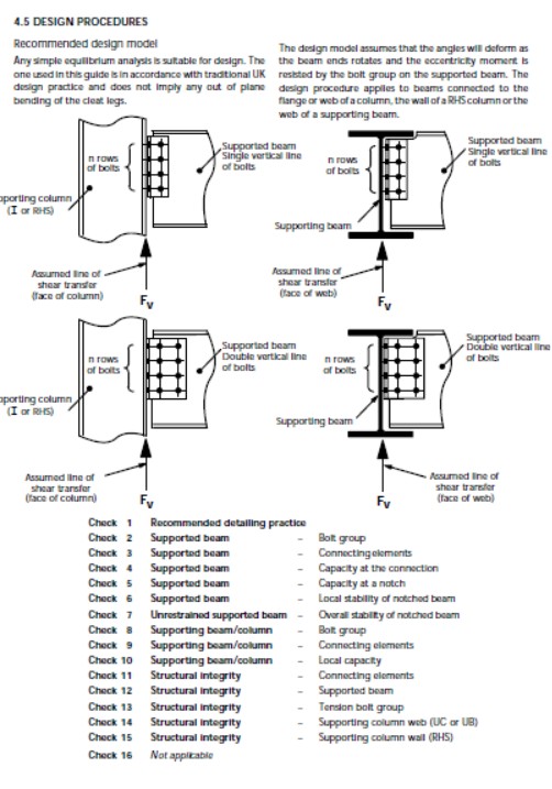
The figure above illustrates the recommended design procedures for single vertical bolt line and double vertical bolt line shear connections attached to:
- Steel Columns (UC/RHS/I Sections)
- Supporting Steel Beams
These detailing methods follow traditional structural steel design philosophy and ensure safe load transfer through the connection.


What is a Beam-to-Column Shear Connection?
A beam-to-column shear connection is a simple steel connection designed mainly to transfer vertical shear forces.
Unlike moment connections, these connections are not intended to resist significant bending moments.
They normally consist of:
- Fin Plate
- End Plate
- Cleat Angle
- Bolts
- Welds
- Supporting Beam or Column
The applied load is represented by:
Fv = Vertical Shear Force
Design Assumptions
The design model assumes:
- Beam end rotates under loading.
- Plate deforms elastically.
- Bolt forces develop gradually.
- Load transfers through the bolt group.
- Shear transfer occurs at the assumed line shown in the design.
No significant moment resistance is assumed.
This simplifies the analysis while remaining conservative for most simple shear connections.
Types of Connections
1. Single Vertical Bolt Line
Characteristics:
- One column of bolts
- Economical
- Easier fabrication
- Used for moderate shear loads
Advantages
- Less drilling
- Lower fabrication cost
- Simple erection
- Faster installation
Typical Applications
- Industrial buildings
- PEB Structures
- Warehouse frames
- Secondary beams
2. Double Vertical Bolt Line
Characteristics
- Two columns of bolts
- Larger shear capacity
- Better load distribution
- Reduced bolt spacing stress
Advantages
- Higher capacity
- Lower force per bolt
- Better stability
- Suitable for heavier beams
Typical Applications
- Heavy industrial structures
- Multi-storey buildings
- Crane girders
- High-load beam connections
Load Transfer Mechanism
The applied shear force travels through the following path:
Beam
↓
Connection Plate
↓
Bolt Group
↓
Supporting Member
↓
Column or Supporting Beam
Every component in this path must safely resist the applied force.
Recommended Structural Design Checks
The design procedure recommends a series of structural checks to ensure adequate strength and serviceability.
Check 1 – Recommended Detailing Practice
Verify:
- Edge distances
- Bolt spacing
- Pitch
- Gauge
- Plate dimensions
- Weld accessibility
Good detailing improves fabrication quality and reduces stress concentration.
Check 2 – Bolt Group Capacity
The bolt group must safely resist:
- Vertical shear
- Combined shear effects
- Bearing forces
Design should consider:
- Bolt shear capacity
- Bearing capacity
- Slip resistance (if required)
Check 3 – Capacity of Connecting Elements
Connecting elements include:
- Fin Plate
- End Plate
- Cleat Angles
- Welds
They must resist:
- Plate bending
- Plate yielding
- Tear-out
- Bearing
Check 4 – Capacity at the Connection
The connection itself must not fail due to:
- Bolt bearing
- Plate rupture
- Net section failure
- Gross yielding
Check 5 – Capacity at a Notch
Where beam flanges are coped or notched:
Verify:
- Remaining web capacity
- Stress concentration
- Local yielding
- Reduced section strength
Check 6 – Local Stability of Notched Beam
Beam notching may reduce web stiffness.
Check:
- Local buckling
- Compression resistance
- Web stability
Check 7 – Overall Stability of Notched Beam
Ensure:
- Lateral stability
- Global buckling resistance
- Adequate remaining section
Check 8 – Bolt Group Verification
Confirm:
- Bolt arrangement
- Load distribution
- Eccentricity effects
- Shear centre location
Check 9 – Connecting Elements
Inspect:
- Plate thickness
- Weld size
- Plate strength
- Fabrication tolerances
Check 10 – Local Capacity
Supporting member should resist:
- Local compression
- Bearing
- Web crippling
Check 11 – Structural Integrity
Provide adequate tying action.
This prevents:
- Progressive collapse
- Connection separation
- Disproportionate failure
Check 12 – Supported Beam
Verify:
- Web strength
- Local yielding
- Web buckling
- Shear resistance
Check 13 – Tension Bolt Group
If connection eccentricity exists:
Check:
- Bolt tension
- Combined shear and tension
- Bolt interaction
Check 14 – Supporting Column Web (UC or UB)
Verify:
- Web yielding
- Web buckling
- Bearing resistance
- Panel zone behaviour
Check 15 – Supporting Column Wall (RHS)
For rectangular hollow sections:
Check:
- Wall bending
- Local yielding
- Plate deformation
- Wall thickness adequacy
Check 16 – Not Applicable
Some connection types may not require this check depending on:
- Geometry
- Loading
- Connection configuration
Difference Between Single and Double Bolt Line Connections
| Feature | Single Bolt Line | Double Bolt Line |
|---|---|---|
| Bolt Columns | 1 | 2 |
| Shear Capacity | Moderate | High |
| Fabrication Cost | Lower | Higher |
| Load Distribution | Moderate | Excellent |
| Plate Width | Narrow | Wider |
| Heavy Beam Suitability | Limited | Excellent |
| Typical Application | Secondary Beams | Primary Beams |
Design Considerations
A safe connection should satisfy:
- Adequate bolt capacity
- Proper weld design
- Plate bending resistance
- Bearing resistance
- Web strength
- Local buckling resistance
- Beam stability
- Column web capacity
- Serviceability
- Constructability
Common Design Mistakes
Avoid these frequent errors:
- Incorrect bolt spacing
- Insufficient edge distance
- Thin fin plates
- Ignoring web buckling
- Underestimating bolt group eccentricity
- Poor weld detailing
- Excessive beam coping
- Incorrect plate thickness
- Ignoring supporting member checks
- Lack of structural integrity verification
Best Practices
✔ Follow the applicable steel design code (e.g., AS 4100, Eurocode 3, AISC 360, or BS standards).
✔ Maintain minimum edge distances and bolt spacing.
✔ Check every component in the load path.
✔ Use double bolt lines for high shear demands.
✔ Avoid excessive beam notching.
✔ Ensure adequate weld quality.
✔ Consider fabrication and erection tolerances.
✔ Review structural integrity requirements.
✔ Inspect supporting member capacity.
✔ Prepare clear fabrication drawings.
Conclusion
Beam-to-column shear connections are fundamental components of steel structures, providing a reliable means of transferring vertical shear while allowing beam rotation. Whether using a single vertical bolt line for economical, moderate-load applications or a double vertical bolt line for higher-capacity connections, a successful design requires thorough verification of bolts, plates, welds, beam webs, notched sections, and supporting members.
By following a systematic design procedure and performing all recommended structural checks, engineers can achieve connections that are safe, economical, and compliant with modern steel design standards.
Frequently Asked Questions (FAQs)
1. What is the purpose of a beam-to-column shear connection?
It transfers vertical shear forces from a supported beam to a supporting column or beam while permitting end rotation.
2. When should a double vertical bolt line be used?
For heavier beams, higher shear loads, or where improved load distribution is required.
3. Why are beam notches checked separately?
Notches reduce the effective web area and may lead to local yielding or buckling if not properly designed.
4. What is the primary load transferred by these connections?
Vertical shear force (Fv).
5. Which components require design verification?
Bolts, welds, connection plates, supported beam web, supporting beam/column web, notched regions, and overall structural integrity.


Leave a Reply