
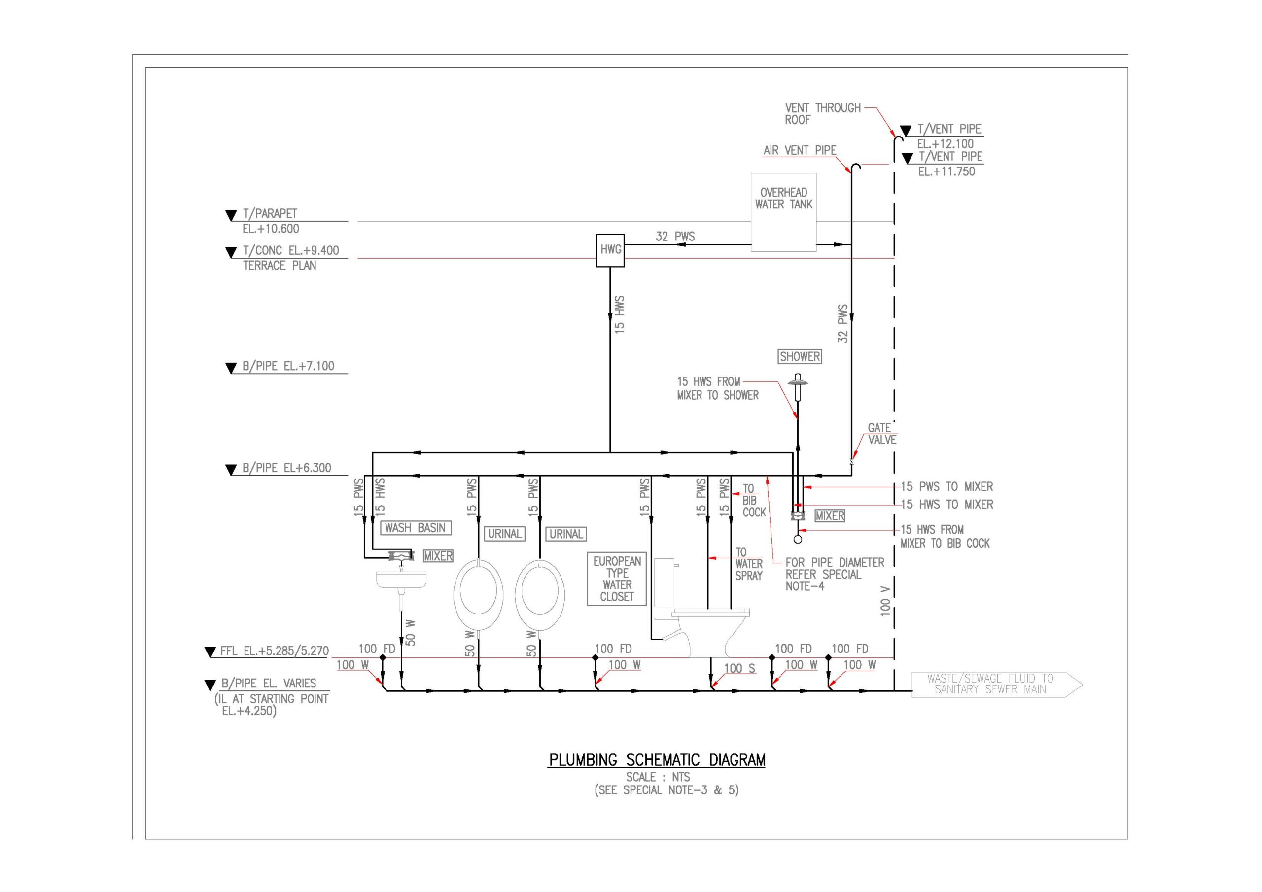
Creating a plumbing scheme drawing involves outlining the entire plumbing system of a building, showing the connections between different fixtures, pipes, valves, and other components. Here are the steps to create a comprehensive plumbing scheme drawing:
Steps to Create a Plumbing Scheme Drawing:
- Gather Building Plans:
- Obtain architectural plans that include floor layouts, elevations, and sections.
- Make sure to have clear measurements and details of all rooms and fixtures.
- Identify Plumbing Fixtures:
- Mark the locations of all plumbing fixtures such as sinks, toilets, showers, bathtubs, washing machines, dishwashers, water heaters, etc.
- Ensure all fixtures are placed according to the design plan.
- Determine Pipe Routes:
- Decide the most efficient routes for hot and cold water supply lines, drain lines, and vent pipes.
- Consider the shortest and most direct paths while minimizing the number of bends and fittings to reduce pressure loss.
- Draw Supply Lines:
- Use solid lines to represent cold water supply lines.
- Use dashed lines to represent hot water supply lines.
- Indicate the main water supply entry point and the routes to each fixture.
- Include details of any water heaters, boilers, or storage tanks.
- Draw Drainage and Vent Lines:
- Use bold lines to represent waste lines (drain lines).
- Use dashed lines to represent vent lines.
- Show the main soil stack and branch lines connecting to each fixture.
- Indicate the sewer connection point or septic system.
- Include Valves and Fittings:
- Mark the location of shut-off valves, check valves, pressure relief valves, and other control devices.
- Indicate fittings like elbows, tees, unions, and couplings.
- Label Components:
- Clearly label all fixtures, pipes, valves, and fittings.
- Include pipe sizes, material specifications, and any relevant codes or standards.
- Add Details and Notes:
- Provide detailed notes on installation requirements, special considerations, and any unique aspects of the plumbing system.
- Include details on insulation, pipe supports, and expansion joints if necessary.
- Review and Finalize:
- Review the drawing for accuracy and completeness.
- Ensure compliance with local building codes and standards.
- Consult with a professional plumber or engineer if needed.
Example of a Simple Plumbing Scheme Drawing:
Here is a basic example of what a plumbing scheme drawing might look like for a single-story house:

[Layout Diagram]
[Water Supply Lines]
– Main water supply line enters at the basement.
– Cold water supply (solid line) runs from the entry point to each fixture.
– Hot water supply (dashed line) runs from the water heater to each fixture needing hot water.
[Drainage and Vent Lines]
– Main soil stack (bold line) runs vertically from the basement through the roof.
– Branch drain lines (bold lines) connect each fixture to the main soil stack.
– Vent lines (dashed lines) connect to the main stack and extend through the roof for proper ventilation.
[Fixtures and Connections]
– Toilet in the bathroom connects to the drain line with a short branch.
– Sink and bathtub in the bathroom connect to the drain line with P-traps and branch lines.
– Kitchen sink connects to the drain line with a P-trap and branch line.
– Washing machine connects to the drain line with a standpipe and trap.
[Valves and Fittings]
– Shut-off valves at each fixture.
– Check valve at the main water entry point.
– Pressure relief valve near the water heater.
[Notes]
– All pipe sizes and materials must comply with local building codes.
– Insulate hot water supply lines to improve energy efficiency.
– Ensure proper slope for all drain lines to facilitate gravity flow.


