
Types of Pile Foundation
- A pile foundation is a series of columns constructed into the ground to transfer loads to a lower level of subsoil.
- Piles are long cylinders made of a strong material, such as concrete or steel.
- Piles are pushed into the ground to act as a steady support for structures built on top of them

Bored Pile –Conventional Tripod Rig
- Boring by DMC Method.
- Boring by Bailor, Chisel method.
- Diameter possible 400 –1500mm.
- Pile can be chiselledinto soft rock& Hard rock.
- Lowering the reinforcement& concreting done by the rig.
- Best method for quality.
- Time consuming.

Bored Pile – Tractor Mounted Hydraulic Rig
- Boring cannot be done in Soft rock & Hard rock.
- Diameter possible is from 150mm –1000mm.
- Cannot do reinforcement lowering & Concreting, Crane required for same.

Bored Pile –Hydraulic Rotary Rig
- Boring done by Auger drilling method – Soil Auger & Rock Auger.
- Diameter possible 500mm -2500mm.
- Boring can be done in soft & HardRock.
- Boring will be faster.
- Reinforcement & Concreting canbe done with this rig.

Driven Pile –Conventional A -Frame Rig
- Piling is done by driving full casing with a pile shoe at the bottom.
- Diameter possible 300mm – 600mm.
- Pile can be done upto hard strata only.
- Progress will be faster.

Driven pile –Pneumatic Hydraulic Driven Rig
- Piling is done by driving full casing with a pile shoe at the bottom.
- Diameter possible 300mm – 600mm.
- Pile can be done upto hard strata only.
- Progress will be faster than A Frame.


Compaction pile –Vibro-Float Method
- By wet method
- By dry method
- Top feeding
- Bottom feeding

Sheet pile
- Using driven pile method
- Vibro-hammer method
- Can be done uptohard strata only.


Categories
- 3D HOUSE DESIGN (34)
- Civil and Structural Design Calculations (76)
- Commercial Plans (9)
- East Facing House Plans (14)
- Engineering Concepts – Civil & Structural (224)
- Excel Spreadsheets (37)
- Free Downloads (49)
- House Plans (57)
- Industrial standards (91)
- North Facing House Plans (15)
- South Facing House Plans (15)
- West Facing House Plans (9)


Product categories
- Civil & Structural Design Calculations (52)
- Commercial Plans (3)
- Excel Spread sheets (47)
- House Plans (13)
- Industrial drawing template (9)
- Uncategorized (0)


Initial load Test
- Test is done on a non-working pile to ascertain the design load.
- Load test is done 2.5 times the design load
- Increment is given at the rate of 20% of design load
- The next increment is given when the rate of displacement is 0.2mm per hour or else after 2 hours
- Increment is continued till 2.5 times is achieved or ultimate failure
- Displacement of pile is measured using calibrated dial gauges
- The result will be based on the lowest values of the following:
- 2/3rdof the load at which the settlement is12 mm for pile diaupto600 mm or
- 2% for pile diabetween 600 to 900 mm and 18 mm for pile diaabove 900
- 50% of the load at which the pile settlement is 10% of the diaof the pile
Routine Load test
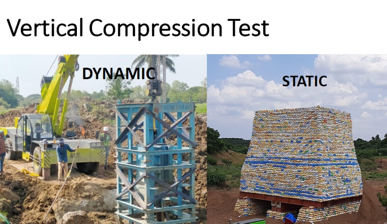
- Vertical compression Test
- Lateral test
- Pull-out test

Vertical compression test static

Lateral test

pull out test

pile integrity test

OUR BLOG POST
- Catch Basin Types and Details
- Eurocode Base Plate Calculator – EN 1993-1-8
- Base Plate Design Calculation AS 4100
- Base Plate Design Calculator CSA A23.3
- Base Plate Design Calculator ACI 318
- Base Plate Design as per IS 800 2007
- East Facing 38×56 House Plan – Ground & First Floor Design with 3BHK + Home Theatre
- Foundation Detail Drawings for Buildings With CAD Files
- Bar Bending Schedule | BBS Calculator For Beam Column and Slab
- Room Paint Calculator | Paint, Primer & Putty Quantity & Cost Estimator
- Load Conversion & Stress Calculator | kN to kg, ton, N, MPa Online
- Water Tank Capacity Calculator – Feet & Meter Conversion (Litres & Gallons)
- Brick Wall Construction Calculator | Calculate Bricks & Cost Instantly |
- Unit Converter – Feet, Inches, cm, mm, Yard to Meter and Vice Versa
- Lifting Analysis of Skid Using Spreader Beam 4-Point
- Base Plate Design as per IS Code | IS 800:2007 Steel Column Base |
- Laser Cut Railing Price in India 2025 | MS & SS CNC Balcony Designs
- MS Balcony Railing Price in India 2026 | Mild Steel Railing Works |
- Stainless Steel with Glass Handrail Price 2026
- Modern Duplex House West Facing 36 x 48
- Pooja Room Door Design
- Modern House 3D Design – Visualizing Your Dream Home
- Balcony Railing Designs for Modern Homes
- Civil Engineering Interview Questions and Important Practical Foundation
- Wind Load Calculation IS 875 Part 3 2015
- Front Elevation Design for Modern Homes
- Road Turning Radius as per IS/IRC Codes and International Standards AASHTO BS/DMRB
- Foundation Design ACI 318 pdf & Excel Download
- Steel Staircase Design
- Front Elevation 20×60 House
- Steel Shed with Mezzanine Floor
- Structural Masonry Designers Manual
- Water Supply Piping Plan and Plumbing Schematic Diagram
- Sump Pit Drawing
- Design of Steel Silo
- Design of Beam to Beam End Plate Connection
- DESIGN OF FLAT SLAB pdf Free Download
- Design of Thrust Block
- Cage Ladder Detail Standard Drawing pdf Free Download
- DESIGN OF BARREL FOR BOX CULVERT pdf Free Download
- Design of Retaining Wall Calculation pdf Free Download
- Analysis and Design of Drain Sump Pit
- Design of High Rise Buildings as per Eurocode
- Design of Steel Shelter as per IS 800
- Octagonal Pedestal Design
- Ring Wall Foundation Design
- Decking Sheet with Concrete – Design Details & Specifications
- Hydrodynamic Load on Tanks | Convective and Impulsive |
- PILE STIFFNESS CALCULATION
- HOUSE PLAN 30 X 60 | SOUTH FACING |
- Concrete Beam Design ACI 318
- Floor Slab Design One Way as per ACI 318
- Floor Slab Design Two way as per ACI 318
- Ceiling Lights and Fan Layout Details
- Floor Tile Design Ideas
- Modern Boundary walls
- Lintel Slab Layout Details
- PILE CAP Detail Drawing
- Eurocode Load Combinations EN 1990 2002
- Expansion Joint Detail and Specification
- Storm Water Drain Detail Drawing
- Thrust Blocks and Restraints Details
- HOUSE PLAN 40 X 50 | SOUTH FACING |
- Octagonal Foundation Reinforcement Details
- Loads and Load Combinations as per AS/NZS 1170.0 2002
- Design of Pump Foundation Dynamic and Static Analysis
- HOUSE PLAN 60 X 40 | WEST FACING |
- Latest Staircase Handrail Design Ideas 40+
- HOUSE PLAN 50 X 50 | SOUTH FACING |
- Electrical Layout For Residential Building
- HOUSE PLAN 29 X 56 | SOUTH FACING |
- Rain Water Gutter and Down Take Systems
- Stormwater Drainage Calculation
- Structural Engineering Design Criteria – American Codes and Standards
- Anchor Bolts Length as per ACI 318-14
- Insert Plate Details & Drawing – Embedded in Concrete Structures
- JOURNAL PAPER GUIDELINES FOR ACSE
- Anchor Bolt Details and Drawing – Embedded in Concrete
- Staircase Layout and Details
- Guard House Layout and Details
- Pump Shed Structural Steel Drawing
- Wind Load Calculations ASCE 7-16 Pdf Free Download
- Column Buckling
- Moody Chart | Moment Reactions for Rectangular Plates |
- Test Pile Drawing Calculation & Guidelines
- Commercial Shop Plan
- Shop Floor Plan
- HOUSE PLAN WITH SHOP 40 x 60 | SOUTH FACING |
- Wind Load Calculation as per Australian Code (AS/NZS 1170.2:2021)
- HOUSE PLAN 30 X 45 | EAST FACING | INTERIOR HOUSE DESIGN |
- HOUSE PLAN 60 x 40 | EAST FACING | APARTMENT TYPE |
- Standard Road Details
- DG Building Architectural Plan & Finishing Schedule
- AMAZING TV UNIT IDEAS 90+ MODELS
- HOUSE PLAN 60 x 50 | EAST FACING |
- Technical Details for Wash Basin Section and Elevation
- Tender Technical Specification for Plumbing and Sanitary works
- HOUSE PLAN 25 x 50 | SOUTH FACING |
- HOUSE PLAN 60 x 45 | SOUTH FACING |
- Fencing Gate Details and Requirements
- Fencing Layout and Details For Transformer Area
- Fencing with Angle Post and Pipe Post Details & Arrangements
- Civil Engineering Formula Book | Pocket Guide pdf Free download |
- HOUSE PLAN 35 x 60 | WEST FACING |
- Transformer Foundation with Soak Pit Layout and Details
- Grating Standard Details and Specifications
- Chequered Plate Standard Details
- Handrail Details for Steel Structural Floors
- Cable Pull Pit Requirements and Details
- Laboratory Building Plan and Architecture Details
- Structural Bolt Details Types Grades and Applications
- HOUSE PLAN 40 x 60 | NORTH FACING |
- Finishing Schedule Drawing for Doors, Windows, and Rolling Shutters
- Workshop Building Architectural Layout
- Calculation of Foundation Bearing Capacity as per IS 6403 – 1981
- Terzaghi’s Bearing Capacity Calculation For Foundations
- DESIGN AND CONSTRUCTION METHOD OF MULTISTORY CONCRETE BUILDINGS
- HOUSE PLAN 60 x 60 | SOUTH FACING |
- Civil Structural Engineering Interview Questions pdf Free Download
- Civil Structural Engineering Interview Questions
- HOUSE PLAN 60 x 30 | EAST FACING |
- HOUSE PLAN 28 x 31 | WEST FACING |
- SHEAR FORCE AND BENDING MOMENT DIAGRAMS WITH FORMULA
- HOUSE PLAN 43 x 66 | SOUTH FACING |
- Canadian Code Seismic Calculation Example
- Weathering Course in RCC Roof
- Rolling Shutter Fixing Detail with RCC Beam
- HOUSE PLAN 35 x 50 | SOUTH FACING |
- APARTMENT PLAN 53 x 62 | EAST & WEST Facing |
- Duct Bank Details and Pipe Sleeves Details
- Handrail Details | Construction Methods and Types of Handrail |
- Details of Ramp
- Design Calculation of Steel Shelter – AISC 360
- Cage Ladder Specification and Detail Drawing
- Staircase Ideas 40+
- Vertical Vessel Foundation Design
- Effective Length for RCC Columns
- DESIGN OF SLABS AS PER IS456
- Design of Staircase Waist Slab
- Monorail Beam Design
- HOUSE PLAN 35 x 50 | SOUTH FACING |
- Concrete Beam Design as per Canadian Code (CSA A23.3-19)
- Wind Load Calculation as per Canadian Code | NBCC 2020 |
- Fencing Detail Drawing
- HOUSE PLAN 40 x 60 | NORTH FACING |
- HOUSE PLAN 60 x 30 | SOUTH FACING |
- RCC Fencing Post Details
- HOUSE PLAN 30 x 40 | NORTH FACING |
- HOUSE PLAN 45 x 45 | WEST FACING |
- HOUSE PLAN 40 x 40 | WEST FACING |
- HOUSE PLAN 30 x 50 | SOUTH FACING |
- Modern House Front Elevation Design
- Transformer Foundation Design
- Gypsum Board False Ceiling Installation
- Box Culvert Design
- Design of Anchor Reinforcement in Concrete Pedestals
- Wind Load Calculation for Pipe Rack
- Apartment House Plan | West Facing 60 x 60 |
- kitchen marble design 30+
- Wind Load Calculation as Per Indian Code
- DESIGN BASIS FOR CIVIL AND STRUCTURAL
- General Specification for Civil and Structural Works
- Green Building
- Fireproofing Details
- Response Spectrum Analysis in STAAD pro
- SHELTER WITH 25T CRANE DRAWING | PEB SHED |
- HOUSE PLAN 20 x 60 | WEST FACING |
- MONORAIL DETAILS
- WEST FACING HOUSE PLAN 50 x 40 | DUPLEX TYPE |
- Side Face Reinforcement as per ACI & IS code
- HOUSE PLANS
- HOUSE PLAN 35 x 50 | EAST FACING |
- HOUSE PLAN 25 x 60 | NORTH FACING |
- HOUSE PLAN 35 x 50 | NORTH FACING |
- Design of Cold-Formed Steel Structures as Per IS 801
- HOUSE PLAN 30 x 40 | EAST FACING |
- HOUSE PLAN 30 x 40| NORTH FACING |
- HOUSE PLAN 20 x 40 | NORTH FACING |
- Lifting Padeye Design
- Corbel Design and Details
- DYNAMIC ANALYSIS USING RESPONSE SPECTRUM ANALYSIS
- Building Load Calculation
- Deep Excavations
- Bathroom Tiles Designs Ideas 50+
- Wooden Main Door Ideas 40+
- Gate Design Ideas 60+
- Structural Design of working pile
- Design of Gantry Girder
- Modern Kitchen Interior Idea Photos 26+
- BEHAVIOUR OF STEEL CHIMNEY UNDER DYNAMIC LOADINGS
- Church Design Drawing
- Seismic Load Calculation as per ASCE 7-16
- 33×66 North Facing Ground Floor Plan with Vastu
- DESIGN OF WIND PRESSURE AS PER EN 1991-1-4
- Best 3D House Elevation Design G+1
- House Plan with Photos | Architect Detail Drawing |
- Trench Details
- PRECAST COVER SLAB DETAILS
- Grade Slab Details
- Resort Cottage Plan
- CONCRETE BATCHING PLANT ARRANGEMENT
- LOAD COMBINATIONS NBCC 2023
- STEEL SHED DRAWING
- Plumbing Drawing
- Pre Engineered Building Design Specification IS Code
- SMALL HOUSE PLAN 28 x 40 | NORTH FACING |
- DESIGN OF PIPERACK STRUCTURE
- BATHROOM FIXTURES AND FITTINGS – European Closet, Urinal & Wash Basin
- DUPLEX HOUSE PLAN 30 x 30 | EAST FACING |
- HOUSE PLAN 29 x 44 | EAST FACING | DUPLEX HOUSE
- Design of Pipe Support Foundation Calculation
- FLAT SLAB DESIGN AND DETAILING
- DIRECT ANALYSIS METHOD AISC 360-05 AND ITS IMPLEMENTATION IN STAAD
- PILE FOUNDATION | TYPE OF PILES | TEST METHODS AND SITE EXECUTION |
- HOUSE PLAN 38 x 58 | BEST EAST FACING | HOME THEATER
- Front Elevation Design 30+
- Design of Concrete Anchor Blocks
- HOUSE PLAN WITH OFFICE AT GROUND FLOOR 27 x 88 | NORTH FACING |
- Design of Shear Key in Base Plate as per IS Code
- HOUSE PLAN 45 x 40 | BEST NORTH FACING BUILDING PLAN |
- BANQUET HALL PLAN 40 x 60 | NORTH FACING |
- MARRIAGE HALL PLAN 33 x 77 | SOUTH FACING |
- COMMERCIAL PLAN 48 x 40 | NORTH FACING |
- APARTMENT TYPE HOUSE PLAN 30 x 80 | EAST FACING | 3BHK
- APARTMENT PLAN 40×50 | EAST FACING | 3BHK |
- Concrete Mix Design Calculations
- PEB Shed Drawing
- HOUSE PLAN 40 x 46 | NORTH FACING |
- DEVELOPMENT LENGTH OF REBAR
Related Posts: