

A well-designed batching plant arrangement ensures efficient concrete production, safety, and ease of maintenance. The arrangement typically includes several key components: aggregate storage bins, conveyor belts, cement silos, water and admixture tanks, the mixer, and control systems. Here’s a detailed guide to arranging a batching plant:
Key Components of a Batching Plant
- Aggregate Storage Bins
- Conveyors and Hoppers
- Cement Silos
- Water and Admixture Tanks
- Mixing Unit (Mixer)
- Control Room
- Weighing Systems
- Loading/Unloading Area
- Batching Control System
Layout Arrangement
1. Aggregate Storage Bins
- Location: Positioned at the start of the batching process, close to the loading area for easy access by loaders.
- Design: Typically consists of multiple bins to store different types of aggregates (sand, gravel, crushed stone).
- Configuration: Often placed in a row or cluster with overhead or ground-level bins.
2. Conveyors and Hoppers
- Function: Transfer aggregates from storage bins to the weighing hoppers and then to the mixer.
- Placement: Conveyor belts run beneath or above the bins, depending on the layout. Inclined conveyors are used to transport materials to elevated positions.
- Hoppers: Located above the mixer to hold and discharge measured quantities of aggregates.
3. Cement Silos
- Location: Placed close to the mixer for quick and efficient transfer of cement.
- Configuration: Vertical silos with screw conveyors or pneumatic systems to move cement to the weighing hopper.
- Capacity: Sized based on plant production requirements and cement supply frequency.
4. Water and Admixture Tanks
- Water Tanks: Positioned near the mixer to minimize piping and ensure accurate measurement.
- Admixture Tanks: Smaller tanks placed adjacent to the water tanks, equipped with dosing pumps for precise measurement and addition.
5. Mixing Unit (Mixer)
- Central Component: Located at the heart of the plant to facilitate the mixing of all components.
- Types: Various types of mixers include twin-shaft mixers, drum mixers, and planetary mixers, chosen based on production needs.
- Accessibility: Ensure easy access for maintenance and inspection.
6. Control Room
- Location: Positioned with a clear view of the entire batching plant, often elevated for better visibility.
- Function: Houses the batching control system, monitoring equipment, and plant operator workspace.
- Safety: Designed to be comfortable and safe for operators, with necessary communication systems.
7. Weighing Systems
- Aggregate Weighing: Placed below the aggregate storage bins to measure the exact quantity of each type of aggregate.
- Cement Weighing: Located between the cement silos and the mixer to ensure accurate measurement.
- Water and Admixture Weighing: Integrated with respective tanks and mixer to precisely control the amount added to the mix.
8. Loading/Unloading Area
- Concrete Loading: Area where the mixed concrete is loaded into transit mixers or trucks.
- Raw Material Unloading: Designated area for receiving and unloading aggregates, cement, and other materials.
- Accessibility: Ensure easy access for trucks and loaders, with sufficient space for maneuvering.
9. Batching Control System
- Integration: Centralized system that controls and monitors the entire batching process.
- Automation: Includes software for automated batching, data logging, and real-time monitoring.
- User Interface: User-friendly interface for operators to input batch recipes, monitor production, and troubleshoot issues.
Sample Layout Plan
Here’s an example layout plan for a medium-sized batching plant:
- Aggregate Storage Area: Multiple bins arranged in a row, with conveyor belts running beneath.
- Cement Silos: Located to the side of the mixer with screw conveyors feeding the weighing hopper.
- Water and Admixture Tanks: Positioned next to the mixer for easy integration with the mixing process.
- Mixer: Centralized unit, accessible from all sides for maintenance.
- Control Room: Elevated position with clear visibility of the entire plant.
- Loading Area: Adjacent to the mixer for efficient loading of transit mixers.
- Unloading Area: Separate space for receiving raw materials, equipped with unloading mechanisms.
Safety and Maintenance Considerations
- Safety: Implement safety barriers, warning signs, and emergency stop buttons throughout the plant.
- Maintenance Access: Ensure easy access to all components for regular maintenance and repairs.
- Dust Control: Install dust suppression systems, especially around aggregate storage and cement silos.
- Waste Management: Provide designated areas for waste collection and disposal to maintain a clean and safe working environment.
By following these guidelines and arranging the components efficiently, you can design a batching plant that maximizes productivity, ensures safety, and simplifies maintenance.
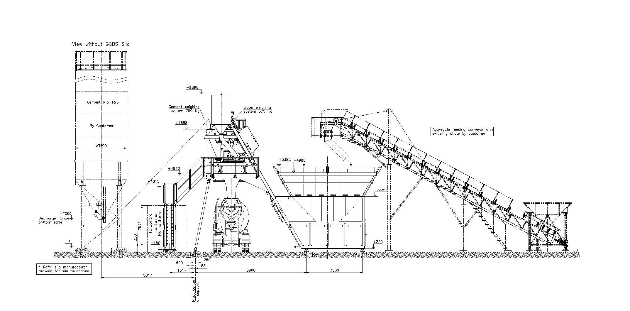
Sample layout
silo sectional view

Categories
- 3D HOUSE DESIGN (19)
- Civil and Structural Design Calculations (41)
- Commercial Plans (9)
- East Facing House Plans (14)
- Engineering Concepts – Civil & Structural (155)
- Excel Spreadsheets (18)
- Free Downloads (17)
- House Plans (51)
- Industrial standards (69)
- North Facing House Plans (15)
- South Facing House Plans (12)
- West Facing House Plans (7)
Calculating the capacity of a batching plant involves understanding several key factors related to the concrete production process. Here’s a step-by-step guide to help you determine the capacity of a batching plant:
Key Factors in Batching Plant Capacity Calculation
- Mixing Time: The time taken to mix each batch.
- Cycle Time: The total time taken for one complete cycle, including loading, mixing, and unloading.
- Number of Batches per Hour: The number of batches the plant can produce in an hour.
- Batch Size: The volume of concrete produced in each batch.
- Effective Working Hours: The actual number of hours the plant operates per day, accounting for downtime, maintenance, and breaks.
Step-by-Step Calculation
1. Determine the Cycle Time
The cycle time (T_cycle) includes:
- Loading time (T_load)
- Mixing time (T_mix)
- Unloading time (T_unload)
Tcycle=Tload+Tmix+TunloadT_{\text{cycle}} = T_{\text{load}} + T_{\text{mix}} + T_{\text{unload}}Tcycle=Tload+Tmix+Tunload
For example:
- Loading time: 5 minutes
- Mixing time: 10 minutes
- Unloading time: 5 minutes
Tcycle=5+10+5=20 minutesT_{\text{cycle}} = 5 + 10 + 5 = 20 \text{ minutes}Tcycle=5+10+5=20 minutes
2. Calculate the Number of Batches per Hour
Convert the cycle time to hours (since 20 minutes is 13\frac{1}{3}31 of an hour):
Number of Batches per Hour=1Tcycle (in hours)=12060=3 batches per hour\text{Number of Batches per Hour} = \frac{1}{T_{\text{cycle (in hours)}}} = \frac{1}{\frac{20}{60}} = 3 \text{ batches per hour}Number of Batches per Hour=Tcycle (in hours)1=60201=3 batches per hour
3. Determine the Batch Size
The batch size (V_batch) depends on the capacity of the mixer. For instance, if the mixer has a capacity of 1 cubic meter:
Vbatch=1 cubic meterV_{\text{batch}} = 1 \text{ cubic meter}Vbatch=1 cubic meter
4. Calculate Hourly Production Capacity
Hourly Capacity=Number of Batches per Hour×Batch Size\text{Hourly Capacity} = \text{Number of Batches per Hour} \times \text{Batch Size}Hourly Capacity=Number of Batches per Hour×Batch Size
Using the example values:
Hourly Capacity=3 batches/hour×1 cubic meter/batch=3 cubic meters/hour\text{Hourly Capacity} = 3 \text{ batches/hour} \times 1 \text{ cubic meter/batch} = 3 \text{ cubic meters/hour}Hourly Capacity=3 batches/hour×1 cubic meter/batch=3 cubic meters/hour
5. Determine Effective Working Hours
Assume the plant operates 8 hours a day with 1 hour for maintenance and breaks, the effective working hours are:
Effective Working Hours=8 hours/day−1 hour/day=7 hours/day\text{Effective Working Hours} = 8 \text{ hours/day} – 1 \text{ hour/day} = 7 \text{ hours/day}Effective Working Hours=8 hours/day−1 hour/day=7 hours/day
6. Calculate Daily Production Capacity
Daily Capacity=Hourly Capacity×Effective Working Hours\text{Daily Capacity} = \text{Hourly Capacity} \times \text{Effective Working Hours}Daily Capacity=Hourly Capacity×Effective Working Hours
Using the example values:
Daily Capacity=3 cubic meters/hour×7 hours/day=21 cubic meters/day\text{Daily Capacity} = 3 \text{ cubic meters/hour} \times 7 \text{ hours/day} = 21 \text{ cubic meters/day}Daily Capacity=3 cubic meters/hour×7 hours/day=21 cubic meters/day
Example Calculation
Let’s consider a batching plant with the following parameters:
- Cycle Time: 20 minutes (0.33 hours)
- Mixer Capacity: 1.5 cubic meters
- Effective Working Hours: 9 hours per day
- Number of Batches per Hour:
Number of Batches per Hour=10.33≈3.03\text{Number of Batches per Hour} = \frac{1}{0.33} \approx 3.03Number of Batches per Hour=0.331≈3.03
- Hourly Production Capacity:
Hourly Capacity=3.03×1.5=4.545 cubic meters/hour\text{Hourly Capacity} = 3.03 \times 1.5 = 4.545 \text{ cubic meters/hour}Hourly Capacity=3.03×1.5=4.545 cubic meters/hour
- Daily Production Capacity:
Daily Capacity=4.545×9≈40.91 cubic meters/day\text{Daily Capacity} = 4.545 \times 9 \approx 40.91 \text{ cubic meters/day}Daily Capacity=4.545×9≈40.91 cubic meters/day
Final Notes
- Ensure that the assumptions for loading, mixing, and unloading times are accurate for your specific plant.
- Consider the plant’s actual operational efficiency, including potential downtime, maintenance needs, and variations in production rates.
- If the plant operates continuously without breaks, adjust the effective working hours accordingly.
By accurately calculating the cycle time, batch size, and effective working hours, you can determine the batching plant’s capacity to meet production requirements.
Recent Posts
- Electrical Layout For Residential Building
- HOUSE PLAN 29 X 56 | SOUTH FACING |
- Rain Water Gutter and Down Take Systems
- Stormwater Drainage Calculation
- Structural Engineering Design Criteria – American Codes and Standards
- Anchor Bolts Length as per ACI 318-14
- Insert Plate Details & Drawing – Embedded in Concrete Structures
- JOURNAL PAPER GUIDELINES FOR ACSE
- Anchor Bolt Details and Drawing – Embedded in Concrete
- Staircase Layout and Details
- Guard House Layout and Details
- Pump Shed Structural Steel Drawing
- ASCE 7-16 Wind Load on Buildings and Structures
- Column Buckling
- Moody Chart | Moment Reactions for Rectangular Plates |
- Test Pile Drawing Calculation & Guidelines
- Commercial Shop Plan
- Shop Floor Plan
- HOUSE PLAN WITH SHOP 40 x 60 | SOUTH FACING |
- Wind Load Calculation as per Australian Code (AS/NZS 1170.2:2021)
- HOUSE PLAN 30 X 45 | EAST FACING | INTERIOR HOUSE DESIGN |
- HOUSE PLAN 60 x 40 | EAST FACING | APARTMENT TYPE |
- Standard Road Details
- DG Building Architectural Plan & Finishing Schedule
- AMAZING TV UNIT IDEAS 90+ MODELS
- HOUSE PLAN 60 x 50 | EAST FACING |
- Technical Details for Wash Basin Section and Elevation
- Tender Technical Specification for Plumbing and Sanitary works
- HOUSE PLAN 25 x 50 | SOUTH FACING |
- HOUSE PLAN 60 x 45 | SOUTH FACING |
- Fencing Gate Details and Requirements
- Fencing Layout and Details For Transformer Area
- Fencing with Angle Post and Pipe Post Details & Arrangements
- Civil Engineering Formula Book | Pocket Guide pdf Free download |
- HOUSE PLAN 35 x 60 | WEST FACING |
- Transformer Foundation with Soak Pit Layout and Details
- Grating Standard Details and Specifications
- Chequered Plate Standard Details
- Handrail Details for Steel Structural Floors
- Cable Pull Pit Requirements and Details
- Laboratory Building Plan and Architecture Details
- Structural Bolt Details Types Grades and Applications
- HOUSE PLAN 40 x 60 | NORTH FACING |
- Finishing Schedule Drawing for Doors, Windows, and Rolling Shutters
- Workshop Building Architectural Layout
- Calculation of Foundation Bearing Capacity as per IS 6403 – 1981
- Terzaghi’s Bearing Capacity Calculation For Foundations
- DESIGN AND CONSTRUCTION METHOD OF MULTISTORY CONCRETE BUILDINGS
- HOUSE PLAN 60 x 60 | SOUTH FACING |
- Civil Structural Engineering Interview Questions pdf Free Download
- Civil Structural Engineering Interview Questions
- HOUSE PLAN 60 x 30 | EAST FACING |
- HOUSE PLAN 28 x 31 | WEST FACING |
- SHEAR FORCE AND BENDING MOMENT DIAGRAMS WITH FORMULA
- HOUSE PLAN 43 x 66 | SOUTH FACING |
- Canadian Code Seismic Calculation Example
- Weathering Course in RCC Roof
- Rolling Shutter Fixing Detail with RCC Beam
- HOUSE PLAN 35 x 50 | SOUTH FACING |
- APARTMENT PLAN 53 x 62 | EAST & WEST Facing |
- Duct Bank Details and Pipe Sleeves Details
- Handrail Details | Construction Methods and Types of Handrail |
- Details of Ramp
- Design Calculation of Steel Shelter – AISC 360
- Cage Ladder Specification and Detail Drawing
- Staircase Ideas 40+
- Vertical Vessel Foundation Design
- Effective Length for RCC Columns
- DESIGN OF SLABS AS PER IS456
- Design of Staircase Waist Slab
- Monorail Beam Design
- HOUSE PLAN 35 x 50 | SOUTH FACING |
- Concrete Beam Design as per Canadian Code (CSA A23.3-19)
- Wind Load Calculation as per Canadian Code | NBCC 2020 |
- Fencing Detail Drawing
- HOUSE PLAN 40 x 60 | NORTH FACING |
- HOUSE PLAN 60 x 30 | SOUTH FACING |
- RCC Fencing Post Details
- HOUSE PLAN 30 x 40 | NORTH FACING |
- HOUSE PLAN 45 x 45 | WEST FACING |
- HOUSE PLAN 40 x 40 | WEST FACING |
- HOUSE PLAN 30 x 50 | SOUTH FACING |
- Modern House Front Elevation Design
- Transformer Foundation Design
- Gypsum Board False Ceiling Installation
- Box Culvert Design
- Design of Anchor Reinforcement in Concrete Pedestals
- Wind Load Calculation for Pipe Rack
- Apartment House Plan | West Facing 60 x 60 |
- kitchen marble design 30+
- Wind Load Calculation as per IS 875 Part 3 2015
- DESIGN BASIS FOR CIVIL AND STRUCTURAL
- General Specification for Civil and Structural Works
- Green Building
- Fireproofing Details
- Response Spectrum Analysis in STAAD pro
- SHELTER WITH 25T CRANE DRAWING | PEB SHED |
- HOUSE PLAN 20 x 60 | WEST FACING |
- MONORAIL DETAILS
- WEST FACING HOUSE PLAN 50 x 40 | DUPLEX TYPE |
- Side Face Reinforcement as per ACI & IS code
- HOUSE PLANS
- HOUSE PLAN 35 x 50 | EAST FACING |
- HOUSE PLAN 25 x 60 | NORTH FACING |
- HOUSE PLAN 35 x 50 | NORTH FACING |
- Design of Cold-Formed Steel Structures as Per IS 801
- HOUSE PLAN 30 x 40 | EAST FACING |
- HOUSE PLAN 30 x 40| NORTH FACING |
- HOUSE PLAN 20 x 40 | NORTH FACING |
- Lifting Padeye Design
- Corbel Design and Details
- DYNAMIC ANALYSIS USING RESPONSE SPECTRUM ANALYSIS
- Building Load Calculation
- Deep Excavations
- Bathroom Tiles Designs Ideas 50+
- Wooden Main Door Ideas 40+
- Gate Design Ideas 60+
- Structural Design of working pile
- Design of Gantry Girder
- Modern Kitchen Interior Idea Photos 26+
- BEHAVIOUR OF STEEL CHIMNEY UNDER DYNAMIC LOADINGS
- Church Design Drawing
- Seismic Load Calculation as per ASCE 7-16
- 33×66 North Facing Ground Floor Plan with Vastu
- DESIGN OF WIND PRESSURE AS PER EN 1991-1-4
- Best 3D House Elevation Design G+1
- House Plan with Photos | Architect Detail Drawing |
- Trench Details
- PRECAST COVER SLAB DETAILS
- Grade Slab Details
- Resort Cottage Plan
- CONCRETE BATCHING PLANT ARRANGEMENT
- LOAD COMBINATIONS NBCC 2023
- STEEL SHED DRAWING
- Plumbing Drawing
- Pre Engineered Building Design Specification IS Code
- SMALL HOUSE PLAN 28 x 40 | NORTH FACING |
- DESIGN OF PIPERACK STRUCTURE
- BATHROOM FIXTURES AND FITTINGS – European Closet, Urinal & Wash Basin
- DUPLEX HOUSE PLAN 30 x 30 | EAST FACING |
- HOUSE PLAN 29 x 44 | EAST FACING | DUPLEX HOUSE
- Design of Pipe Support Foundation Calculation
- FLAT SLAB DESIGN AND DETAILING
- DIRECT ANALYSIS METHOD AISC 360-05 AND ITS IMPLEMENTATION IN STAAD
- PILE FOUNDATION | TYPE OF PILES | TEST METHODS AND SITE EXECUTION |
- HOUSE PLAN 38 x 58 | BEST EAST FACING | HOME THEATER
- Front Elevation Design 30+
- Design of Concrete Anchor Blocks
- HOUSE PLAN WITH OFFICE AT GROUND FLOOR 27 x 88 | NORTH FACING |
- Design of Shear Key in Base Plate as per IS Code
- HOUSE PLAN 45 x 40 | BEST NORTH FACING BUILDING PLAN |
- BANQUET HALL PLAN 40 x 60 | NORTH FACING |
- MARRIAGE HALL PLAN 33 x 77 | SOUTH FACING |
- COMMERCIAL PLAN 48 x 40 | NORTH FACING |
- APARTMENT TYPE HOUSE PLAN 30 x 80 | EAST FACING | 3BHK
- APARTMENT PLAN 40×50 | EAST FACING | 3BHK |
- Concrete Mix Design Calculations
- PEB Shed Drawing
- HOUSE PLAN 40 x 46 | NORTH FACING |
- DEVELOPMENT LENGTH OF REBAR