
Designing 🌧️ Stormwater Drainage systems is essential to ensure the efficient collection and disposal of surface runoff from rainfall. Proper pipe sizing ensures that the stormwater is carried safely without causing flooding, ponding, or structural damage.
📘 1. Key Formula: Rational Method
The Rational Method is widely used for stormwater pipe sizing in small urban drainage systems: Q=C ⋅ i ⋅ A
Where:
- Q = Peak runoff (m³/s or cfs)
- C = Runoff coefficient (depends on surface type)
- i = Rainfall intensity (mm/hr or in/hr)
- A = Catchment area (hectares or acres)
📐 2. Step-by-Step Pipe Sizing Procedure
🔹 Step 1: Define Catchment Area
Measure the area contributing runoff to the pipe. Use site drawings or GIS tools.
- Units: hectares (ha) or square meters (m²)
🔹 Step 2: Assign Runoff Coefficient (C)
Based on surface type:
| Surface | C value |
|---|---|
| Paved / Asphalt | 0.85–0.95 |
| Roof surface | 0.75–0.95 |
| Lawn / grass area | 0.10–0.35 |
| Concrete surface | 0.90–0.95 |
🔹 Step 3: Determine Rainfall Intensity (i)
Use local IDF curves or rainfall data for the required return period (e.g., 10-year, 25-year storm).
- Units: mm/hr or in/hr
🔹 Step 4: Calculate Peak Flow (Q)
Q = (C⋅i⋅A) / 360
- Result in m³/s if using mm/hr and hectares
- Adjust for multiple catchments if needed
🔹 Step 5: Select Pipe Diameter
Use Manning’s Formula for flow in pipes: Q = 1/ n ⋅ A ⋅ R ^ 2/3 ⋅ S ^1/2
Where:
- n = Manning’s roughness coefficient (typically 0.013 for concrete, 0.011 for PVC)
- A = Cross-sectional area of pipe
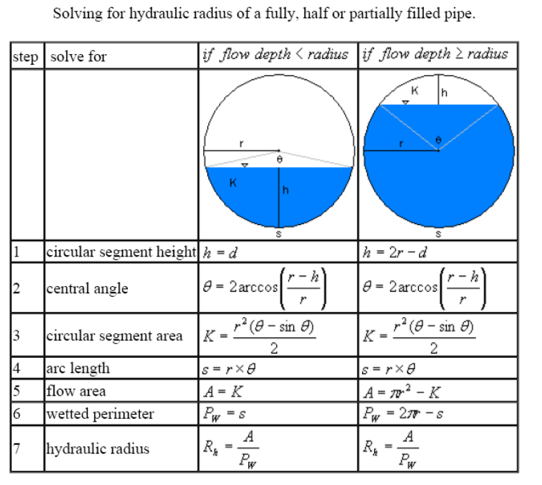
- R = Hydraulic radius = A / P (P = wetted perimeter)
- S = Slope of pipe
🧰 Example Calculation
- Catchment Area (A) = 0.5 ha
- Surface = Pavement ⇒ C = 0.90`
- Rainfall Intensity (i) = 75 mm/hr
- Pipe Slope (S) = 0.005 (0.5%)
- Manning’s n = 0.013
Q = 0.9 ⋅ 75 ⋅ 0.5 / 360 = 0.094 m3/s
Use Manning’s formula to back-calculate required pipe diameter that will carry 0.094 m³/s.

f = arc sin (0.4r/r) = 0.412 radians = 23.578 degrees
q = 180+2*f = 3.965 radians = 227.156 degrees
Sample Calculation for an 8″ (0.203mm) pipe. D = 0.203
FLOW AREA
Method 1

= 0.102^2*(227.156*pi/180-SIN(227.156))/2
= 0.024 m2
Method 2

= 0.102^2*(3.965/2+COS(0.412)*SIN(0.412)
= 0.024 m2
WETTED PERIMETER

= 0.102*3.965
= 0.402 m
B. CALCULATION OF DISCHARGE CAPACITY, Qc
Manning’s Formula
Assume flow depth equal to 0.7 times the pipe diameter for the max. design flow rate.
Qc = 3600 * A * R2/3 * S 1/2 / n
Where,
D = Pipe Diameter, m
A = Flow Area, m2
P = Wetted Perimeter, m
S = Bed Gradient
n = Roughness Coefficient
R = Hydraulic Radius, m
= A/P
C.CALCULATION OF VELOCITIES
Qc = V * A
Where ,
v = velocity, m/s
A = Flow Area, m2
vmax ≤ 3 m/s
vmin ≥ 0.75 m/s Qcmin = 0.2 x Qcmax

✅ Design Tips
- Always check full flow capacity (pipe not surcharged)
- Include minimum self-cleansing velocity (≥ 0.6 m/s)
- Consider future expansion (use 25–50% extra capacity)
- Provide manholes and catchpits at changes in slope or direction
📚 Codes & References
- IS 1172, IS 2065, IS 3370, and SP 35
- US EPA SWMM software
- StormCAD / Civil 3D for advanced modeling
- Local municipal design manuals
- Rain Water Gutter and Down Take Systems
 Typical Gutter and Downpipe Systems: An Overview Understanding Rain Water… Read more: Rain Water Gutter and Down Take Systems
 - Stormwater Drainage Calculation
 Designing 🌧️ Stormwater Drainage systems is essential to ensure the… Read more: Stormwater Drainage Calculation
 - Structural Engineering Design Criteria – American Codes and Standards
 In the United States, structural engineering design is governed by… Read more: Structural Engineering Design Criteria – American Codes and Standards
 - Insert Plate Details & Drawing – Embedded in Concrete Structures
 Insert plates are embedded steel plates installed in concrete elements… Read more: Insert Plate Details & Drawing – Embedded in Concrete Structures
 - Anchor Bolt Details and Drawing – Embedded in Concrete
 Anchor bolts are crucial elements in structural and foundation systems,… Read more: Anchor Bolt Details and Drawing – Embedded in Concrete
 - Staircase Layout and Details
 A staircase is an essential architectural element that provides vertical… Read more: Staircase Layout and Details
 - Guard House Layout and Details
 A guard house, also known as a security cabin or… Read more: Guard House Layout and Details
 - Pump Shed Structural Steel Drawing
 A pump shed is a small but critical structure designed… Read more: Pump Shed Structural Steel Drawing
 - Column Buckling
 Introduction Structural dynamics problems deal with structures in motion. Examples… Read more: Column Buckling
 - Moody Chart | Moment Reactions for Rectangular Plates |
 Introduction to Moody’s Chart for Slab Design Moody’s Chart is… Read more: Moody Chart | Moment Reactions for Rectangular Plates |
 - Standard Road Details
 Rigid & Flexible Road Details – Drawings & Requirements Road… Read more: Standard Road Details
 - DG Building Architectural Plan & Finishing Schedule
 A DG (Diesel Generator) building is a dedicated structure designed… Read more: DG Building Architectural Plan & Finishing Schedule
 - Technical Details for Wash Basin Section and Elevation
 A wash basin is an essential plumbing fixture used in… Read more: Technical Details for Wash Basin Section and Elevation
 - Tender Technical Specification for Plumbing and Sanitary works
 Tender Technical Specification for Factory buildings – Plumbing and Sanitary… Read more: Tender Technical Specification for Plumbing and Sanitary works
 - Fencing Gate Details and Requirements
 A fencing gate is an essential component of any secure… Read more: Fencing Gate Details and Requirements
 - Fencing Layout and Details For Transformer Area
 Transformer fencing is an essential safety requirement to protect electrical… Read more: Fencing Layout and Details For Transformer Area
 - Fencing with Angle Post and Pipe Post Details & Arrangements
 Fencing using angle posts and pipe (dia) posts is widely… Read more: Fencing with Angle Post and Pipe Post Details & Arrangements
 - Civil Engineering Formula Book | Pocket Guide pdf Free download |
 Civil Engineering Formula Book – Essential Reference for Engineers Civil… Read more: Civil Engineering Formula Book | Pocket Guide pdf Free download |
 - Transformer Foundation with Soak Pit Layout and Details
 A transformer foundation with a soak pit is designed to… Read more: Transformer Foundation with Soak Pit Layout and Details
 - Grating Standard Details and Specifications
 Grating Details and Requirements Gratings are open-grid flooring systems made… Read more: Grating Standard Details and Specifications
 - Chequered Plate Standard Details
 Chequered Plate Standard Details A chequered plate (also known as… Read more: Chequered Plate Standard Details
 - Handrail Details for Steel Structural Floors
 Details and Requirements of Handrails for Steel Structural Floors Handrails… Read more: Handrail Details for Steel Structural Floors
 - Cable Pull Pit Requirements and Details
 Cable Pull Pit Requirements and Details A cable pull pit… Read more: Cable Pull Pit Requirements and Details
 - Laboratory Building Plan and Architecture Details
 Laboratory Building Plan Requirements for Industries Designing an industrial laboratory… Read more: Laboratory Building Plan and Architecture Details
 - Structural Bolt Details Types Grades and Applications
 Structural Bolt Details: Types, Grades, and Applications Structural bolts are… Read more: Structural Bolt Details Types Grades and Applications
 - Finishing Schedule Drawing for Doors, Windows, and Rolling Shutters
 How to Prepare a Finishing Schedule Drawing for Doors, Windows,… Read more: Finishing Schedule Drawing for Doors, Windows, and Rolling Shutters
 - Workshop Building Architectural Layout
 How to Prepare an Architectural Layout for a Workshop Building… Read more: Workshop Building Architectural Layout
 - Calculation of Foundation Bearing Capacity as per IS 6403 – 1981
 The IS 6403:1981 standard provides guidelines for calculating the bearing… Read more: Calculation of Foundation Bearing Capacity as per IS 6403 – 1981
 - Terzaghi’s Bearing Capacity Calculation For Foundations
 How to Calculate Bearing Capacity of a Foundation The bearing… Read more: Terzaghi’s Bearing Capacity Calculation For Foundations
 - DESIGN AND CONSTRUCTION METHOD OF MULTISTORY CONCRETE BUILDINGS
 The recommendations which should be taken into account in designing… Read more: DESIGN AND CONSTRUCTION METHOD OF MULTISTORY CONCRETE BUILDINGS
 - Civil Structural Engineering Interview Questions pdf Free Download
 Are you preparing for a Civil or Structural Engineering job… Read more: Civil Structural Engineering Interview Questions pdf Free Download
 - Civil Structural Engineering Interview Questions
 Civil & Structural Engineering Interview Questions Here’s a comprehensive list… Read more: Civil Structural Engineering Interview Questions
 - SHEAR FORCE AND BENDING MOMENT DIAGRAMS WITH FORMULA
 Introduction Figures 1 through 32 provides a series of shear… Read more: SHEAR FORCE AND BENDING MOMENT DIAGRAMS WITH FORMULA
 - Weathering Course in RCC Roof
 Procedure for Weathering Course in RCC Roof A weathering course… Read more: Weathering Course in RCC Roof
 - Rolling Shutter Fixing Detail with RCC Beam
 Rolling Shutter Fixing Detail with RCC Beam Rolling shutters are… Read more: Rolling Shutter Fixing Detail with RCC Beam
 - Duct Bank Details and Pipe Sleeves Details
 Duct Bank Details and Pipe Sleeves Details A duct bank… Read more: Duct Bank Details and Pipe Sleeves Details
 - Handrail Details | Construction Methods and Types of Handrail |
 Methods of Typical Handrail Construction in RCC Structures Handrails in… Read more: Handrail Details | Construction Methods and Types of Handrail |
 - Details of Ramp
 Methods and Details of Ramp Construction Ramps are inclined surfaces… Read more: Details of Ramp
 - Design Calculation of Steel Shelter – AISC 360
 PURPOSE AND SCOPE The scope of this document is to… Read more: Design Calculation of Steel Shelter – AISC 360
 - Cage Ladder Specification and Detail Drawing
 Detailed Specification for Steel Cage Ladders Steel cage ladders are… Read more: Cage Ladder Specification and Detail Drawing
 - Concrete Beam Design as per Canadian Code (CSA A23.3-19)
 Concrete Beam Design as per Canadian Code (CSA A23.3-19) The… Read more: Concrete Beam Design as per Canadian Code (CSA A23.3-19)
 - Fencing Detail Drawing
 Fencing Detail Drawing Requirements To create a comprehensive fencing detail… Read more: Fencing Detail Drawing
 - RCC Fencing Post Details
 Requirements for RCC Fence Posts RCC (Reinforced Cement Concrete) posts… Read more: RCC Fencing Post Details
 - Gypsum Board False Ceiling Installation
 Gypsum board false ceiling installation layout and details Installing a… Read more: Gypsum Board False Ceiling Installation
 - Design of Anchor Reinforcement in Concrete Pedestals
 Design of Anchor Reinforcement in Concrete Pedestals Pedestal rebars parallel… Read more: Design of Anchor Reinforcement in Concrete Pedestals
 - Wind Load Calculation as per IS 875 Part 3 2015
 Wind Load Calculation Wind speed -33m/sec From Ground floor to… Read more: Wind Load Calculation as per IS 875 Part 3 2015
 - DESIGN BASIS FOR CIVIL AND STRUCTURAL
 Design Basis for Civil and Structural SPECIFIC DESIGN REQUIREMENTS [CIVIL]… Read more: DESIGN BASIS FOR CIVIL AND STRUCTURAL
 - General Specification for Civil and Structural Works
 CONTENTS CLAUSE NO. DESCRIPTION PAGE NO. 1.00.00 INTRODUCTION 1 2.00.00… Read more: General Specification for Civil and Structural Works
 - Green Building
 A green building is a structure designed, constructed, and operated… Read more: Green Building
 - Fireproofing Details
 Fireproofing, also known as fire-resistive protection, is crucial for structural… Read more: Fireproofing Details
 - Response Spectrum Analysis in STAAD pro
 In STAAD.Pro, combining loads using the SRSS (Square Root of… Read more: Response Spectrum Analysis in STAAD pro
 - SHELTER WITH 25T CRANE DRAWING | PEB SHED |
 Designing a shelter with a 25-ton capacity crane involves structural… Read more: SHELTER WITH 25T CRANE DRAWING | PEB SHED |
 - MONORAIL DETAILS
 To create a monorail drawing connected to a concrete beam,… Read more: MONORAIL DETAILS
 - Lifting Padeye Design
 Padeye is a plate or attachment point commonly used in… Read more: Lifting Padeye Design
 - Corbel Design and Details
 DESIGN OF CORBEL A corbel is a short cantilever used… Read more: Corbel Design and Details
 - BEHAVIOUR OF STEEL CHIMNEY UNDER DYNAMIC LOADINGS
 Introducing Steel Chimneys or Stack The behavior of steel chimneys… Read more: BEHAVIOUR OF STEEL CHIMNEY UNDER DYNAMIC LOADINGS
 - DESIGN OF WIND PRESSURE AS PER EN 1991-1-4
 The calculation for wind load as per EN 1991-1-4 for a gas plant located in a terrain category I includes parameters such as a fundamental basic wind velocity of 32.30 m/s, a directional factor and season factor of 1.00 each, and various terrain factors and roughness lengths. Wind turbulence intensity and peak velocity pressure vary with height.
 - Grade Slab Details
 Paving or Grade slab Details A grade slab, also known… Read more: Grade Slab Details
 - Resort Cottage Plan
 Designing a cottage plan involves creating a cozy, functional, and… Read more: Resort Cottage Plan
 - CONCRETE BATCHING PLANT ARRANGEMENT
 A well-designed batching plant arrangement ensures efficient concrete production, safety,… Read more: CONCRETE BATCHING PLANT ARRANGEMENT
 - LOAD COMBINATIONS NBCC 2023
 LOAD COMBINATIONS CANADIAN CODE NBCC 2023 The National Building Code… Read more: LOAD COMBINATIONS NBCC 2023
 - STEEL SHED DRAWING
 1. Plan View (Top View): Outline of the Shed: Show… Read more: STEEL SHED DRAWING
 - Plumbing Drawing
 Creating a plumbing scheme drawing involves outlining the entire plumbing… Read more: Plumbing Drawing
 - Pre Engineered Building Design Specification IS Code
 Pre-Engineered Building PEB PEB stands for Pre-Engineered Building. It refers… Read more: Pre Engineered Building Design Specification IS Code
 - BATHROOM FIXTURES AND FITTINGS – European Closet, Urinal & Wash Basin
 BATHROOM FIXTURES AND FITTINGS European Closet – fitting dimensions For… Read more: BATHROOM FIXTURES AND FITTINGS – European Closet, Urinal & Wash Basin
 - Design of Pipe Support Foundation Calculation
 Design of Pipe Support Foundation Calculation Piping Input: GA and… Read more: Design of Pipe Support Foundation Calculation
 - Design of Concrete Anchor Blocks
 STATIC ANALYSIS & DESIGN OF PIPE ANCHOR BLOCK FOUNDATION DESIGN… Read more: Design of Concrete Anchor Blocks
 - PEB Shed Drawing
 PEB – Industrial standard architectural drawing with all details.
Leave a Reply