
Cable Pull Pit Requirements and Details
A cable pull pit (also called a cable pulling chamber or pull box) is an essential component of underground electrical and telecommunication systems. It is used to facilitate cable pulling, maintenance, and jointing for electrical and fiber optic cables. These pits reduce friction and tension in long cable runs and provide access points for repairs.
1. Purpose of a Cable Pull Pit
✔️ Provides an accessible location for cable pulling and maintenance.
✔️ Reduces tension and strain on cables in long underground runs.
✔️ Allows for cable jointing, splicing, and re-routing.
✔️ Ensures safety and compliance with electrical and telecom standards.
✔️ Protects underground cables from external damage and water ingress.
2. Key Design Considerations
a. Location and Spacing
- Placed at every 30-50 meters in long cable runs.
- Located at bends, intersections, and entry points to buildings.
- Ensure clear access for maintenance personnel.
b. Pit Size & Depth
- The size depends on cable type, quantity, and access requirements.
- Typical pit dimensions:
- Small pits: 600mm x 600mm x 600mm (for telecom cables).
- Medium pits: 900mm x 900mm x 900mm (for electrical cables).
- Large pits: 1200mm x 1200mm x 1200mm (for high-voltage cables).
c. Pit Material Selection
- Precast RCC (Reinforced Concrete) – Durable, used for heavy-duty applications.
- FRP (Fiber-Reinforced Plastic) / Composite – Lightweight, corrosion-resistant.
- HDPE or Polypropylene – Used in telecom networks.
- Brick Masonry with RCC Slab Cover – Traditional construction for small projects.
d. Cover and Load Rating
- Covers must comply with IS 12592, BS EN 124, or ASTM D2321 standards.
- Load classifications:
- Light duty (A15, B125) – Pedestrian areas.
- Medium duty (C250) – Driveways and sidewalks.
- Heavy duty (D400, E600) – Roads and industrial areas.


3. Structural Details of a Cable Pull Pit
a. Typical Construction Layers
- Base Slab: 150-200mm thick RCC slab for stability.
- Side Walls: RCC or masonry with plastered internal surfaces.
- Drainage Layer: Gravel/sand bed to prevent water accumulation.
- Cable Entry & Exit: PVC/HDPE pipes with smooth bends for cable routing.
- Pit Cover: Hinged or bolted for security and easy access.
b. Cable Management Inside the Pit
- Cable support brackets to hold cables in position.
- Cable saddles or rollers to reduce bending stress.
- Labeling and tagging for easy identification.


4. Safety & Compliance Requirements
- Non-slip covers to prevent accidents.
- Earthing provisions for electrical cable pits.
- Fire-resistant materials in high-risk areas.
- Drainage system to prevent waterlogging.
- Lockable covers to prevent unauthorized access.
5. Cable Pull Pit Spacing Guidelines
| Cable Type | Pit Spacing (m) | Recommended Depth (mm) |
|---|---|---|
| LV Power Cables | 30 – 50 | 600 – 900 |
| HV Power Cables | 40 – 60 | 900 – 1200 |
| Fiber Optic Cables | 50 – 100 | 600 – 800 |
| Telecom Cables | 40 – 80 | 600 – 900 |
| Road Crossing Pits | As per requirement | 900 – 1200 |
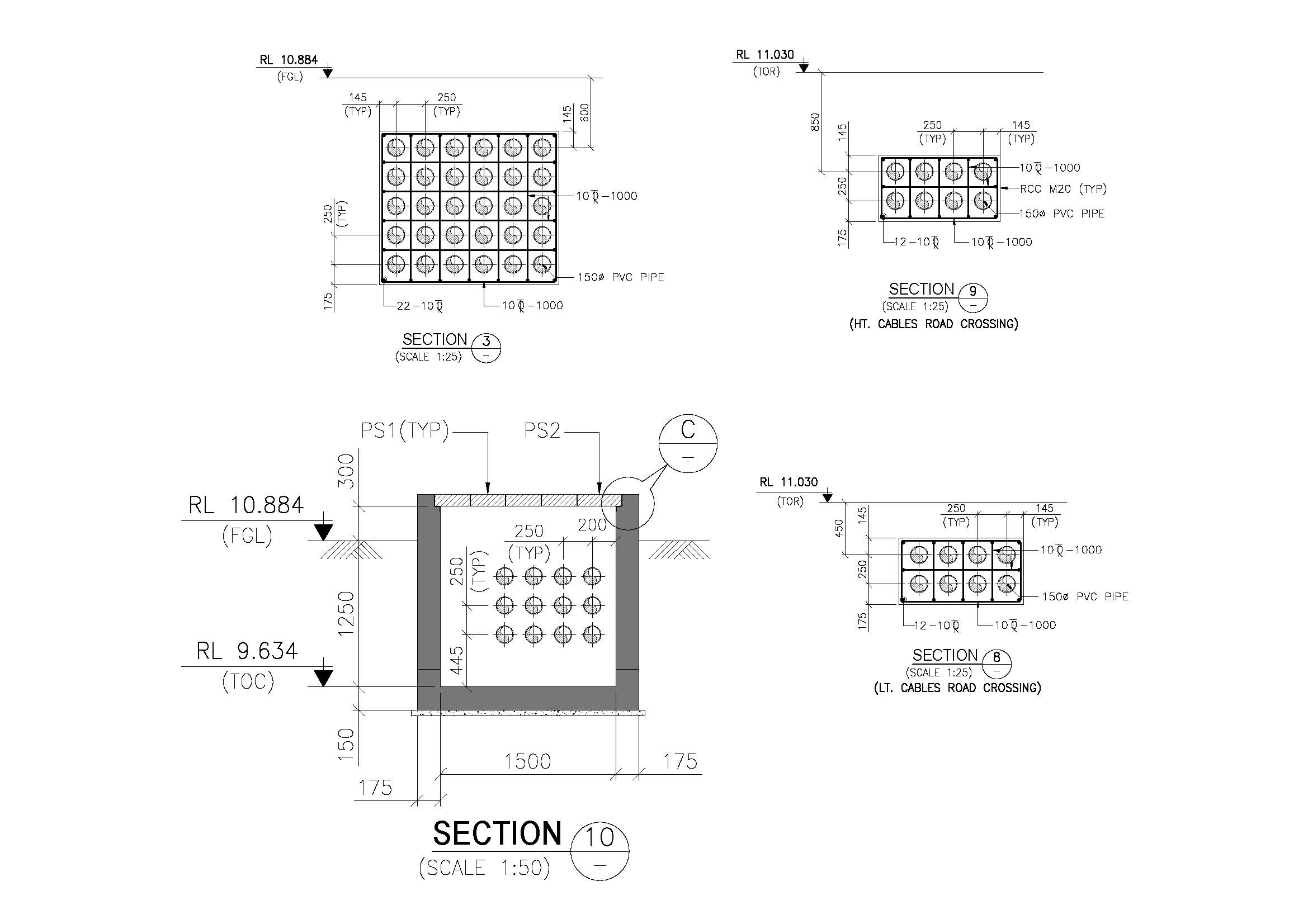
6. Example Cable Pull Pit Drawing
Key Components in the Drawing:
- Pit Dimensions – Width, depth, and entry/exit ducts.
- Cover Specifications – Load-bearing capacity.
- Cable Routing Details – Entry points and conduit sizes.
- Drainage & Ventilation Features – Preventing water accumulation.
7. Software for Cable Pull Pit Design
- AutoCAD – For 2D pit layout and section drawings.
- Revit (BIM) – For 3D modeling and MEP integration.
- SketchUp – For conceptual visualization.
- Civil 3D – For infrastructure utility design.
8. Conclusion
A well-designed cable pull pit ensures efficient cable management, maintenance access, and structural durability in underground electrical and communication networks. By following industry standards, selecting the right materials, and maintaining proper spacing, you can achieve a reliable and long-lasting underground cabling system.
- Catch Basin Types and Details

- Foundation Detail Drawings for Buildings With CAD Files

- Bar Bending Schedule | BBS Calculator For Beam Column and Slab

- Room Paint Calculator | Paint, Primer & Putty Quantity & Cost Estimator

- Brick Wall Construction Calculator | Calculate Bricks & Cost Instantly |

- Unit Converter – Feet, Inches, cm, mm, Yard to Meter and Vice Versa

- Civil Engineering Interview Questions and Important Practical Foundation

- Road Turning Radius as per IS/IRC Codes and International Standards AASHTO BS/DMRB

- Steel Staircase Design

- Steel Shed with Mezzanine Floor

- Structural Masonry Designers Manual

- Water Supply Piping Plan and Plumbing Schematic Diagram

- Sump Pit Drawing

- Cage Ladder Detail Standard Drawing pdf Free Download

- Lintel Slab Layout Details

- PILE CAP Detail Drawing

- Eurocode Load Combinations EN 1990 2002

- Expansion Joint Detail and Specification

- Storm Water Drain Detail Drawing

- Thrust Blocks and Restraints Details

- Octagonal Foundation Reinforcement Details

- Design of Pump Foundation Dynamic and Static Analysis

- Electrical Layout For Residential Building

- Rain Water Gutter and Down Take Systems

- Stormwater Drainage Calculation

- Structural Engineering Design Criteria – American Codes and Standards

- Insert Plate Details & Drawing – Embedded in Concrete Structures

- Anchor Bolt Details and Drawing – Embedded in Concrete

- Staircase Layout and Details

- Guard House Layout and Details

- Pump Shed Structural Steel Drawing

- Column Buckling

- Moody Chart | Moment Reactions for Rectangular Plates |

- Standard Road Details

- DG Building Architectural Plan & Finishing Schedule

- Technical Details for Wash Basin Section and Elevation

- Tender Technical Specification for Plumbing and Sanitary works

- Fencing Gate Details and Requirements

- Fencing Layout and Details For Transformer Area

- Fencing with Angle Post and Pipe Post Details & Arrangements

- Civil Engineering Formula Book | Pocket Guide pdf Free download |

- Transformer Foundation with Soak Pit Layout and Details

- Grating Standard Details and Specifications

- Chequered Plate Standard Details

- Handrail Details for Steel Structural Floors

- Cable Pull Pit Requirements and Details

- Laboratory Building Plan and Architecture Details

- Structural Bolt Details Types Grades and Applications

- Finishing Schedule Drawing for Doors, Windows, and Rolling Shutters

- Workshop Building Architectural Layout

- Calculation of Foundation Bearing Capacity as per IS 6403 – 1981

- Terzaghi’s Bearing Capacity Calculation For Foundations

- DESIGN AND CONSTRUCTION METHOD OF MULTISTORY CONCRETE BUILDINGS

- Civil Structural Engineering Interview Questions pdf Free Download

- Civil Structural Engineering Interview Questions

- SHEAR FORCE AND BENDING MOMENT DIAGRAMS WITH FORMULA

- Weathering Course in RCC Roof

- Rolling Shutter Fixing Detail with RCC Beam

- Duct Bank Details and Pipe Sleeves Details

- Handrail Details | Construction Methods and Types of Handrail |

- Details of Ramp

- Design Calculation of Steel Shelter – AISC 360

- Cage Ladder Specification and Detail Drawing

- Concrete Beam Design as per Canadian Code (CSA A23.3-19)

- Fencing Detail Drawing

- RCC Fencing Post Details

- Gypsum Board False Ceiling Installation

- Design of Anchor Reinforcement in Concrete Pedestals

- Wind Load Calculation as Per Indian Code

- DESIGN BASIS FOR CIVIL AND STRUCTURAL

- General Specification for Civil and Structural Works

- Green Building

- Fireproofing Details

- Response Spectrum Analysis in STAAD pro

- SHELTER WITH 25T CRANE DRAWING | PEB SHED |

- MONORAIL DETAILS

- Lifting Padeye Design

- Corbel Design and Details

- BEHAVIOUR OF STEEL CHIMNEY UNDER DYNAMIC LOADINGS

- DESIGN OF WIND PRESSURE AS PER EN 1991-1-4

- Grade Slab Details

- Resort Cottage Plan

- CONCRETE BATCHING PLANT ARRANGEMENT

- LOAD COMBINATIONS NBCC 2023

- STEEL SHED DRAWING

- Plumbing Drawing

- Pre Engineered Building Design Specification IS Code

- BATHROOM FIXTURES AND FITTINGS – European Closet, Urinal & Wash Basin

- Design of Pipe Support Foundation Calculation

- Design of Concrete Anchor Blocks

- PEB Shed Drawing
