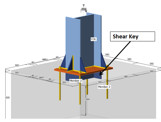
DESIGN OF SHEAR KEY as per IS800 and concrete checks are IS450-2000
Base plate design as per IS800 codal provisions, Shear key is provided to increase the resistance to sliding. The shear key is generally an extension of the vertical stem and extends below the bottom of the base to help reducing the thickness of the anchor bolts by absorbing the shear force.
Base Plate length = 650 mm
Base Plate Width = 650 mm
Maximum Horizontal shear F = 53.000 kN Ref: Annexure G.5
Characteristic comp. strength fck = 30 N/mm² IS:456-2000 Table 2
Allowable bearing stress sb = 0.25fck IS:456-2000 cl. 34.4
= 7.5 N/mm2
Bearing Stress factor = 1.25
Depth required D = F/(1.25*sb*L)
= 11 mm
Provide shear key depth below grout 100 mm
L
= 500
Bearing pressure on the plate p = F/(D*L)
= 1.06 N/mm2
The
shear key is designed as a plate is fixed on two sides and free on other two
sides.
D
= 150
Max. Bending moment = 1.06 x 100 x (100/2+50)
= 10600 N.mm
Bending Stress factor = 1.33
Allowable bending stress = 185*1.33
= 246.05 N/mm2
Thickness of shear key t = sqrt(6M/sbc)
= 16.1 mm
Thickness provided = 25 mm OK
Provide shear key as 500 x 150 x
25mm
L/C:
115
Fz – Direction Node:
64
Maximum Horizontal shear F = 51.500 kN Ref:
Annexure A2
Characteristic comp. strength fck = 30 N/mm² IS:456-2000 Table 2
Allowable bearing stress sb = 0.25fck IS:456-2000 cl. 34.4
= 7.5 N/mm2
Bearing Stress factor = 1.25
Depth required D = F/(1.25*sb*L)
= 10.99 mm
Provide shear key depth below grout 100 mm
Bearing pressure on the plate p = F/(D*L)
= 1.0 N/mm2
The
shear key is designed as a plate is fixed on two sides and free on other two
sides.
L
= 500
D
= 150
Max. Bending moment = 1.03 x 100 x (100/2+50)
= 10300 N.mm
Bending Stress factor = 1.33
Allowable bending stress = 0.66*230*1.33
= 201.894 N/mm2
Thickness of shear key t = sqrt(6M/sbc)
= 17.5 mm
Thickness provided = 25 mm OK
Provide shear key as 500 x 150 x
25mm
BREAKOUT CHECK FOR PEDESTALÂ Â Â Â Â Â Â Â Â Â Â Â Â Â Â Â Â Â Â Â Â Â Â Â Â Â Â Â Â Â Â Â Â Â Â Â Â Â Â Â Â Â Â Â Â Â Â Â Â Â Â Â Â Â Â Â Â Â Â Â Â Â Â Â Â Â Â Â Â Â Â Â Â Â Â Â Â Â Â Â Â Â Â Â Â Â Â Â Â Â Â Â Â Â Â Â Â Â Â Â Â Â Â Â Â Â Â
      Check for shear break-out strength                                                                                         Â
           FX direction                                                                                                    Â
           For M30 tc,max                         =        2.2      N/mm2    IS:456, Table 24Â
           Maximum Horizontal Shear                  Fx       =        100.000           kN   Â
           Actual shear stress                       =        100*1000/(375*750)                                       Â
                                            =        0.36     N/mm2     Assuming minimum p of 0.15%                                                Â
           For M30 tc,perm                         =        0.2      N/mm2      IS:456, Table 23                  Â
        Design Shear Vs                                             =        (0.36-0.2)*(375*750)                    Â
                                             =        45000.00         N                               Â
           Spacing assumed in pedsestal height (Sv)        =        200      mm     `                     Â
           Effective depth (d)                        =        375      mm                            Â
           No. of legs assumed                                      Â
=Â Â Â Â Â Â Â Â 10Â Â Â Â Â Â Â Â Â Â Â Â Â Â Â Â Â Â Â Â Â Â Â Â Â Â Â Â Â Â Â Â Â Â Â Â Â Â Â Â Â Â Â
                                                                       Vs       =        ssv . Asv .d                                      Â
                                                                                                          Sv                                         Â
           Dia of leg required                                           =           SQRT(45000*200/(230*10*PI()*0.25*375))                                           Â
                                                                                    =        3.64     mm                            Â
Â
           Dia of leg provided                                           =        10       mm
Recent Posts
- Lifting Padeye Design
- Corbel Design and Details
- DYNAMIC ANALYSIS USING RESPONSE SPECTRUM ANALYSIS
- building Load calculation
- Deep Excavations
- Bathroom Tiles Designs Ideas 50+
- Wooden Main Door Ideas 40+
- Gate Design Ideas 60+
- Structural Design of working pile
- Design of Gantry Girder
- Modern Kitchen Interior Idea Photos 26+
- BEHAVIOUR OF STEEL CHIMNEY UNDER DYNAMIC LOADINGS
- Church Design Drawing
- Seismic Load Calculation as per ASCE 7-16
- 33×66 North Facing Ground Floor Plan with Vastu
- DESIGN OF WIND PRESSURE AS PER EN 1991-1-4
- Best 3D House Elevation Design G+1
- House Plan with Photos | Architect Detail Drawing |
- Trench Details
- PRECAST COVER SLAB DETAILS
- Grade Slab Details
- Resort Cottage Plan
- CONCRETE BATCHING PLANT ARRANGEMENT
- LOAD COMBINATIONS NBCC 2023
- STEEL SHED DRAWING
- Plumbing Drawing
- Pre Engineered Building Design Specification IS Code
- SMALL HOUSE PLAN 28 x 40 | NORTH FACING |
- DESIGN OF PIPERACK STRUCTURE
- BATHROOM FIXTURES AND FITTINGS – European Closet, Urinal & Wash Basin
- DUPLEX HOUSE PLAN 30 x 30| EAST FACING |
- HOUSE PLAN 29 x 44 | EAST FACING | DUPLEX HOUSE
- Design of Pipe Support Foundation Calculation
- FLAT SLAB DESIGN AND DETAILING
- DIRECTÂ ANALYSIS METHOD AISC 360-05 AND ITS IMPLEMENTATIONÂ IN STAAD
- PILE FOUNDATION | TYPE OF PILES | TEST METHODS AND SITE EXECUTION |
- HOUSE PLAN 38 x 58 | BEST EAST FACING | HOME THEATER
- Front Elevation Design 30+
- Design of Concrete Anchor Blocks
- HOUSE PLAN WITH OFFICE AT GROUND FLOOR 27 x 88 | NORTH FACING |
- Design of Shear Key in Base Plate as per IS Code
- HOUSE PLAN 45 x 40 | BEST NORTH FACING BUILDING PLAN |
- BANQUET HALL PLAN 40 x 60 | NORTH FACING |
- MARRIAGE HALL PLAN 33 x 77 | SOUTH FACING |
- COMMERCIAL PLAN 48 x 40 | NORTH FACING |
- APARTMENT TYPE HOUSE PLAN 30 x 80 | EAST FACING | 3BHK
- APARTMENT PLAN 40×50 | EAST FACING | 3BHK |
- Concrete Mix Design Calculations
- PEB Shed Drawing
- HOUSE PLAN 40 x 46 | North Facing |
- DEVELOPMENT LENGTH OF REBAR