
COG Shift, Moment Calculation & Sling Forces for STAAD Pro
In heavy equipment skids, direct 4-point lifting without a spreader beam often results in high sling forces, torsional effects, and uneven load sharing due to Centre of Gravity (COG) shift.
A spreader beam is commonly introduced to control sling angles, redistribute loads, and improve structural stability during lifting.
This article explains moment calculation due to COG shift, sling force evaluation, and STAAD Pro load application for a 4-point lifted skid with a spreader beam.
Why Use a Spreader Beam?

Using a spreader beam provides:
- Reduced sling angle at skid lifting points
- Lower local stresses at lifting lugs
- Controlled load sharing between lift points
- Reduced torsion due to COG eccentricity
📌 Important:
The spreader beam does not remove COG eccentricity, but it reduces secondary stresses and sling amplification.
Lifting Configuration Description
Lifting Arrangement
- Crane hook → Spreader beam (top slings)
- Spreader beam → 4 skid lifting points (bottom slings)
- Bottom slings assumed near vertical
Sling Angles
- Top sling angle (crane to spreader): 45°
- Bottom sling angle (spreader to skid): ≤ 10° (nearly vertical)
Given Data (Same Skid Geometry)
Skid Lifting Point Geometry
- Length between lift points (X-direction) = 1.8 m
- Width between lift points (Y-direction) = 0.6 m
COG Offset
- Eccentricity in X = 0.3 m
- Eccentricity in Y = 0.1 m
Total Design Lifted Weight
| Description | Value |
|---|---|
| Skid + equipment | 220 kN |
| Dynamic amplification factor | 1.10 |
W=220×1.10=242 kN
This is the total vertical load transferred to the spreader beam.
5️⃣ Moment Due to COG Shift (UNCHANGED by Spreader Beam)
Moment About Y-Axis (COG shift in X)
My=W×ex My=242×0.3=72.6 kN\cdotpm
Moment About X-Axis (COG shift in Y)
Mx=W×ey Mx=242×0.1=24.2 kN\cdotpm
📌 Key Insight:
Spreader beam improves force transfer but global moments due to COG remain the same.
Vertical Load Distribution at Skid Lifting Points
Base Equal Reaction
V0=4242=60.5 kN
Moment Distribution Method
Coordinates of lift points:
| Point | X (m) | Y (m) |
|---|---|---|
| A | +0.9 | +0.3 |
| B | +0.9 | −0.3 |
| C | −0.9 | +0.3 |
| D | −0.9 | −0.3 |
Load Increment Due to X-Eccentricity
ΔVx=∑x2My=4×0.9272.6=22.4 kN
Load Increment Due to Y-Eccentricity
ΔVy=∑y2Mx=4×0.3224.2=67.2 kN
Resulting Vertical Reactions
| Lift Point | Vertical Load (kN) |
|---|---|
| A | 60.5 + 22.4 + 67.2 = 150.1 |
| B | 60.5 + 22.4 − 67.2 = 15.7 |
| C | 60.5 − 22.4 + 67.2 = 105.3 |
| D | 60.5 − 22.4 − 67.2 = −29.1 (Slack) |
⚠ Negative reaction indicates loss of tension → unacceptable.
Practical Engineering Redistribution (With Spreader Beam)
With a spreader beam:
- Bottom slings act nearly vertical
- Load redistribution is more stable
- Minimum load per sling is enforced
Adopted Conservative Distribution
| Lift Point | % of W | Vertical Load (kN) |
|---|---|---|
| A | 40% | 96.8 |
| B | 30% | 72.6 |
| C | 20% | 48.4 |
| D | 10% | 24.2 |
✔ Widely accepted in ISO 19901-6 and EPC lifting practices
✔ Ensures no slack slings
Sling Force Calculation (WITH Spreader Beam)
Bottom Slings (Near Vertical)
Assume bottom sling angle = 10°Tbottom=cos10∘V
| Lift Point | Vertical Load (kN) | Bottom Sling Force (kN) |
|---|---|---|
| A | 96.8 | 98.3 |
| B | 72.6 | 73.7 |
| C | 48.4 | 49.1 |
| D | 24.2 | 24.6 |
📌 Major benefit of spreader beam:
Bottom sling forces ≈ vertical loads (no amplification).
Top Slings (Crane to Spreader)
Total load on spreader beam = 242 kN
Assume 2 top slings at 45°Ttop=cos45∘242/2=171 kN per sling
Loads to Apply in STAAD Pro (Skid Analysis)
Load Case 1 – Self Weight
LOAD 1 SELF WEIGHT
SELFWEIGHT Y -1
Load Case 2 – Spreader Beam Lifting Loads
LOAD 2 SPREADER BEAM LIFTING
JOINT LOAD
101 FY 96.8
102 FY 72.6
103 FY 48.4
104 FY 24.2
✔ Apply vertical upward forces at skid lifting nodes
✔ Spreader beam forces are not modelled in skid STAAD model
Load Combination
LOAD COMB 3 LIFTING DESIGN
1.25 1 1.25 2
COG Load Application in STAAD Pro
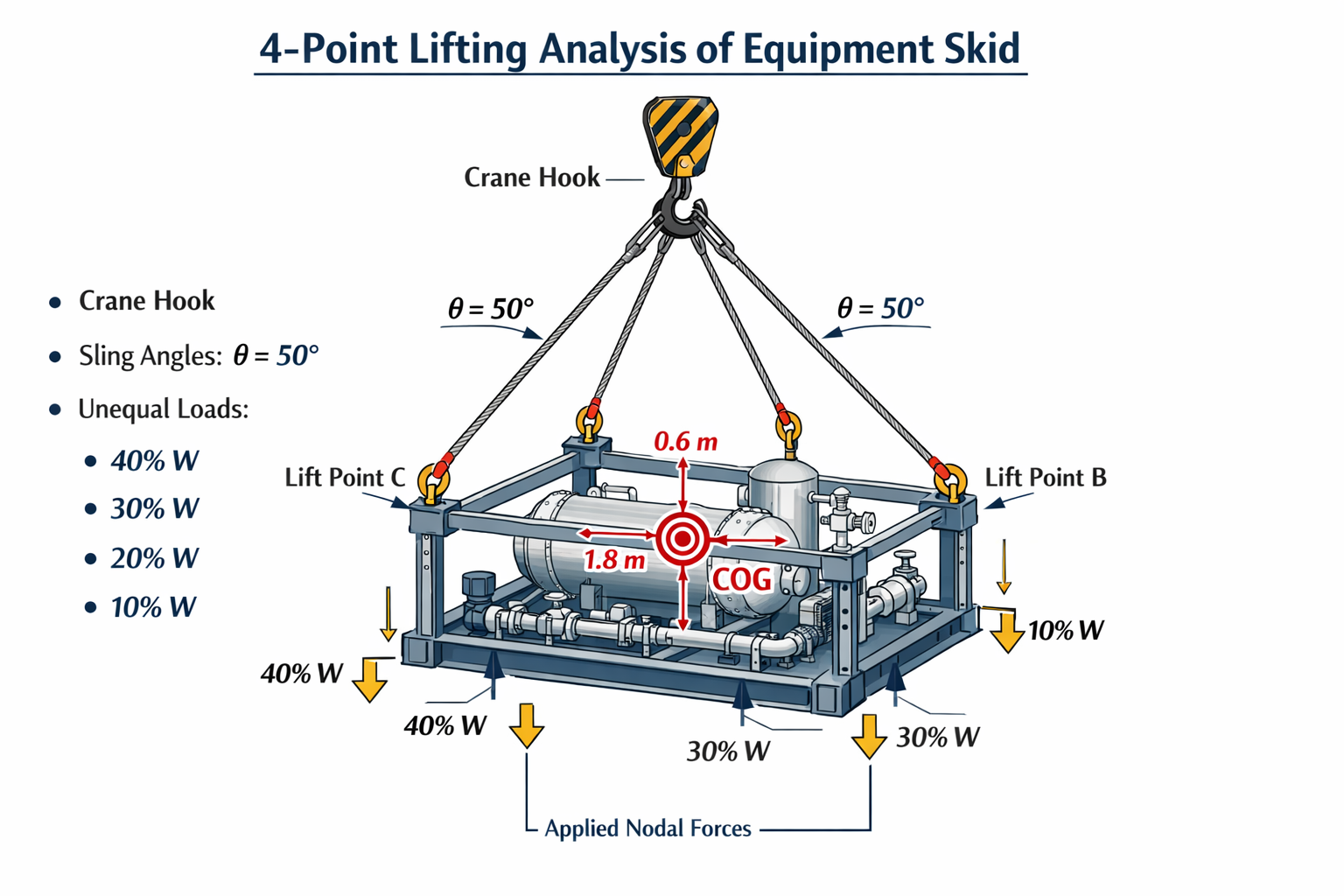
4-Point Lifting of Equipment Skid (Based on Above Diagram)
Assumptions from the Picture
- Lifting type: 4-point lifting
- Crane hook with 4 slings
- Sling angle from vertical: θ = 50°
- COG offset toward one corner
- Unequal load distribution:
- Lift Point A = 40% W
- Lift Point B = 30% W
- Lift Point C = 20% W
- Lift Point D = 10% W
This is a conservative and industry-accepted assumption for asymmetric skids.
Step 1: Total Lifted Weight
Assume (example – you can edit values):
| Item | Weight (kN) |
|---|---|
| Skid steel frame | 120 |
| Equipment & piping | 80 |
| Misc / allowance | 20 |
| Total Structure Weight (Ws) | 220 kN |
Dynamic Amplification Factor
Normal lifting → 1.10W=220×1.10=242 kN
This 242 kN is the design lifted weight.
Step 2: Vertical Load Share at Each Lift Point
| Lift Point | % of W | Vertical Load (kN) |
|---|---|---|
| A | 40% | 0.40 × 242 = 96.8 |
| B | 30% | 0.30 × 242 = 72.6 |
| C | 20% | 0.20 × 242 = 48.4 |
| D | 10% | 0.10 × 242 = 24.2 |
✔ These are the vertical reactions that STAAD must balance.
Step 3: Sling Tension Calculation (for Check)
STAAD does not need sling tension, but it is required for rigging verification.T=cos50∘V
| Lift Point | Vertical V (kN) | Sling Tension T (kN) |
|---|---|---|
| A | 96.8 | 150.6 |
| B | 72.6 | 113.0 |
| C | 48.4 | 75.3 |
| D | 24.2 | 37.7 |
📌 Use these values to size slings, shackles, pad eyes.
Step 4: How to Apply Loads in STAAD Pro
Key Rule
DO NOT provide supports
The structure must be free in space, lifted only by nodal forces.
Load Case 1 – Self Weight
LOAD 1 SELF WEIGHT
SELFWEIGHT Y -1
Load Case 2 – Lifting Loads (COG Balanced)
Assume node numbers:
- Lift Point A → Node 101
- Lift Point B → Node 102
- Lift Point C → Node 103
- Lift Point D → Node 104
Apply UPWARD forces (positive Y):
LOAD 2 LIFTING LOADS
JOINT LOAD
101 FY 96.8
102 FY 72.6
103 FY 48.4
104 FY 24.2
✔ This exactly represents the COG-based unequal lifting shown in the picture.
Step 5: Load Combination for Lifting
Recommended Design Combination
LOAD COMB 3 LIFTING DESIGN
1.25 1 1.25 2
Meaning:1.25×(Self Weight + Lifting Load)
This covers:
- Crane impact
- Minor COG shift
- Rigging tolerances
Step 6: How STAAD Confirms COG Correctness
After analysis:
- Check sum of lifting reactions
- It must equal total lifted weight
- Check deformation shape → no excessive twist
- Highest stresses will occur near:
- Lift points
- Bottom longitudinal beams
- Eurocode Base Plate Calculator – EN 1993-1-8
 Introduction Base plates are critical components in steel structures, transferring… Read more: Eurocode Base Plate Calculator – EN 1993-1-8
 - Base Plate Design Calculation AS 4100
 Introduction In structural steel design, the base plate is a… Read more: Base Plate Design Calculation AS 4100
 - Base Plate Design Calculator CSA A23.3
 Introduction Steel column base plates transfer loads from the column… Read more: Base Plate Design Calculator CSA A23.3
 - Base Plate Design Calculator ACI 318
 Introduction Designing a steel column base plate is a critical… Read more: Base Plate Design Calculator ACI 318
 - Base Plate Design as per IS 800 2007
 Introduction (Anchor Bolts Outside & Inside Column Flange) Base plates… Read more: Base Plate Design as per IS 800 2007
 - Bar Bending Schedule | BBS Calculator For Beam Column and Slab
 Managing the Bar Bending Schedule (BBS) is one of the… Read more: Bar Bending Schedule | BBS Calculator For Beam Column and Slab
 - Room Paint Calculator | Paint, Primer & Putty Quantity & Cost Estimator
 Looking to renovate your room? Our Room Paint, Primer &… Read more: Room Paint Calculator | Paint, Primer & Putty Quantity & Cost Estimator
 - Load Conversion & Stress Calculator | kN to kg, ton, N, MPa Online
 Load Conversion & Stress Calculator for Civil and Structural Engineers… Read more: Load Conversion & Stress Calculator | kN to kg, ton, N, MPa Online
 - Water Tank Capacity Calculator – Feet & Meter Conversion (Litres & Gallons)
 Water Tank Capacity Calculator with Unit Conversion Accurate water storage… Read more: Water Tank Capacity Calculator – Feet & Meter Conversion (Litres & Gallons)
 - Brick Wall Construction Calculator | Calculate Bricks & Cost Instantly |
 Introduction Building a brick wall requires accurate planning to avoid… Read more: Brick Wall Construction Calculator | Calculate Bricks & Cost Instantly |
 - Unit Converter – Feet, Inches, cm, mm, Yard to Meter and Vice Versa
 Length Unit Converter 🌙 Toggle Dark Mode Length Unit Converter… Read more: Unit Converter – Feet, Inches, cm, mm, Yard to Meter and Vice Versa
 - Lifting Analysis of Skid Using Spreader Beam 4-Point
 COG Shift, Moment Calculation & Sling Forces for STAAD Pro… Read more: Lifting Analysis of Skid Using Spreader Beam 4-Point
 - Base Plate Design as per IS Code | IS 800:2007 Steel Column Base |
 Introduction In steel structures, the base plate is a critical… Read more: Base Plate Design as per IS Code | IS 800:2007 Steel Column Base |
 - Wind Load Calculation IS 875 Part 3 2015
 Below is a compact, practical guide you can use on… Read more: Wind Load Calculation IS 875 Part 3 2015
 - Road Turning Radius as per IS/IRC Codes and International Standards AASHTO BS/DMRB
 1. Turning Radius as per Indian Standards (IRC/IS Codes) In… Read more: Road Turning Radius as per IS/IRC Codes and International Standards AASHTO BS/DMRB
 - Foundation Design ACI 318 pdf & Excel Download
 In ACI 318 (American Concrete Institute’s Building Code Requirements for… Read more: Foundation Design ACI 318 pdf & Excel Download
 - Design of Steel Silo
 1. Introduction Steel silo is, typical uses (grain, cement, powders),… Read more: Design of Steel Silo
 - Design of Beam to Beam End Plate Connection
 Beam end-to-end connections (splices) ensure continuity and safe transfer of… Read more: Design of Beam to Beam End Plate Connection
 - DESIGN OF FLAT SLAB pdf Free Download
 🔹 What is a Flat Slab? A flat slab is… Read more: DESIGN OF FLAT SLAB pdf Free Download
 - Design of Thrust Block
 Thrust blocks are one of the most important structural components… Read more: Design of Thrust Block
 - DESIGN OF BARREL FOR BOX CULVERT pdf Free Download
 Box culvert design according to IRC 6 (Standard Specifications and Code… Read more: DESIGN OF BARREL FOR BOX CULVERT pdf Free Download
 - Design of Retaining Wall Calculation pdf Free Download
 Retaining walls are essential structural elements in civil engineering, used… Read more: Design of Retaining Wall Calculation pdf Free Download
 - Analysis and Design of Drain Sump Pit
 Introduction A sump pit, commonly used in buildings, industrial plants,… Read more: Analysis and Design of Drain Sump Pit
 - Design of Steel Shelter as per IS 800
 Designing a steel shelter requires a clear understanding of structural… Read more: Design of Steel Shelter as per IS 800
 - Octagonal Pedestal Design
 Designing an octagon pedestal as per ACI (American Concrete Institute)… Read more: Octagonal Pedestal Design