
A Practical Structural Drawing Guide
Introduction
Footing drawings form the foundation of all structural execution. Clear footing plans and sections help site engineers, supervisors, and contractors understand:
- Exact footing size and location
- Column positioning
- Depth and construction sequence
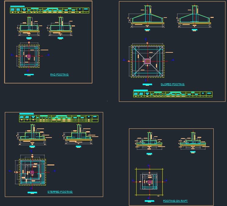
This guide explains how to draw, read, locate, and present the following footing types using actual structural drawings:
- Isolated Footing
- Footing on Raft
- Sloped Footing
- Stepped Footing
1️⃣ Isolated Footing – Drawing Explanation

What is an Isolated Footing?
An isolated footing supports a single column and transfers load directly to the soil. It is the most commonly used footing in low- to mid-rise buildings.
How to Identify the Drawing
- One column at the center
- Square or rectangular footing
- Independent from other footings
How to Read the Drawing
Plan View
- Shows full footing size
- Column located at center (or slightly offset if required)
- Reinforcement direction shown with arrows
Section Views (X–X / Y–Y)
- Soil at bottom
- PCC / leveling course
- RCC footing
- Column rising from footing
How to Locate on Site
- Use grid lines or centerline references
- Match column centerline with footing center
- Excavation size taken from footing plan
How to Present in Structural Drawings
✔ Clear footing plan
✔ Minimum two sectional views
✔ Column clearly centered and aligned
✔ Footing title as “ISOLATED FOOTING”
Drafting Tip:
Never overload the plan—depths and construction sequence must be explained in sections.
2️⃣ Footing on Raft – Drawing Explanation
What This Drawing Shows
- A column footing resting over a raft slab
- Raft reinforcement passing continuously below
- Footing acting as a thickened portion of the raft
How to Read the Drawing
- Plan shows column position on raft
- Sections show footing integrated with raft thickness
- No separate excavation beyond raft level
How to Present Properly
✔ Label clearly as FOOTING ON RAFT
✔ Show raft slab continuously
✔ Provide both X-X and Y-Y sections
Site Note:
This is not an isolated footing—mislabeling causes major site errors.
3️⃣ Sloped Footing – Drawing Explanation
How to Identify a Sloped Footing
- Top surface slopes from column face to edge
- Bottom surface remains flat
- Economical concrete profile
How to Read the Drawing
- Plan shows full footing footprint
- Diagonal or sloping indicators point toward column
- Section clearly shows slope geometry
How to Present Clearly
✔ Slope shown only in section views
✔ Thickness at column and edge marked
✔ Clean, uncluttered plan
Common Site Issue:
Without a proper section, sloped footing is often mistaken as stepped.
4️⃣ Stepped Footing – Drawing Explanation

How to Identify a Stepped Footing
- Multiple horizontal steps
- Uniform step heights
- Wider base than top
How to Read the Drawing
- Plan shows bottom-most size
- Sections show individual step levels
- Column passes through step center
How to Present Correctly
✔ Each step dimensioned clearly
✔ Steps labeled (Step-1, Step-2, etc.)
✔ Reinforcement shown step-wise
Drafting Tip:
Steps must be emphasized in section views, not crowded in plan.
5️⃣ General Footing Drawing Presentation Rules
✔ Always provide Plan + at least 2 Sections
✔ Column centerline must match footing center
✔ PCC / leveling layer shown separately
✔ Dimensions readable without zoom
✔ Clear footing titles:
- ISOLATED FOOTING
- FOOTING ON RAFT
- SLOPED FOOTING
- STEPPED FOOTING
6️⃣ Free CAD File Download (Editable)
A free editable CAD file will be provided containing:
- Isolated footing
- Footing on raft
- Sloped footing
- Stepped footing

- Australian Wind Load Calculator as per AS/NZS 1170.2:2021
 Australian Wind Load Calculator | AS/NZS 1170.2:2021 Australian Wind Load… Read more: Australian Wind Load Calculator as per AS/NZS 1170.2:2021
 - Wind Load Calculator as per IS 875 Part 3:2015
 Industrial Shed Wind Load Calculator | IS 875 Part 3:2015… Read more: Wind Load Calculator as per IS 875 Part 3:2015
 - RCC Staircase Detail Drawing free pdf Download
 Reinforced Cement Concrete (RCC) staircases are one of the most… Read more: RCC Staircase Detail Drawing free pdf Download
 - Modern 35×40 House Design with Premium Front Elevation
 Building a dream home on a 35×40 plot is one… Read more: Modern 35×40 House Design with Premium Front Elevation
 - Pipe Rack GA Drawing Layout
 Image – Typical Pipe Rack GA Drawing Explanation The above… Read more: Pipe Rack GA Drawing Layout
 - House Plan 30×40 West Facing | 2BHK Luxury Floor Design |
 Designing a compact yet spacious home on a 30×40 plot… Read more: House Plan 30×40 West Facing | 2BHK Luxury Floor Design |
 - Bund Wall Detail Drawing for Tank Farm and Oil Storage Area
 Introduction A bund wall (also called a dyke wall or… Read more: Bund Wall Detail Drawing for Tank Farm and Oil Storage Area
 - Dyke Wall Layout and Detail | Oil Tank Containment Systems |
 Introduction A dyke wall (also called a bund wall or… Read more: Dyke Wall Layout and Detail | Oil Tank Containment Systems |
 - Apartment Plan 28×32 West Facing with Modern Elevation
 This project showcases a well-planned 30×40 west-facing apartment design featuring… Read more: Apartment Plan 28×32 West Facing with Modern Elevation
 - How to Assign LY and LZ in STAAD for Steel Structures (With and Without Bracing)
 🔹 What is LY and LZ? In STAAD.Pro: These define… Read more: How to Assign LY and LZ in STAAD for Steel Structures (With and Without Bracing)
 - HOUSE PLAN 35 X 41 | EAST FACING |
 Designing a perfect home requires a balance of functionality, aesthetics,… Read more: HOUSE PLAN 35 X 41 | EAST FACING |
 - EDG Building Power Cable Layout with MTO Guide
 Introduction An Emergency Diesel Generator (EDG) system is a critical… Read more: EDG Building Power Cable Layout with MTO Guide
 - HOUSE PLAN EAST FACING 30 X 40
 Designing a compact yet functional home on a 30’ x… Read more: HOUSE PLAN EAST FACING 30 X 40
 - Septic Tank Drawing and Details
 Septic tanks are widely used in residential buildings for on-site… Read more: Septic Tank Drawing and Details
 - Holding Tank Detail
 Introduction A holding tank, also known as a water sump… Read more: Holding Tank Detail
 - Rain Water Harvesting System pdf Book Download
 TABLE OF CONTENTS 1.0 INTRODUCTION 3 2.0 CHAPTER 1 4… Read more: Rain Water Harvesting System pdf Book Download
 - Galvanized Gate | Design Details and Specifications Guide |
 Introduction Industrial galvanized gates are designed for heavy-duty usage, high… Read more: Galvanized Gate | Design Details and Specifications Guide |
 - Soak Pit Details | Seepage Pit |
 Introduction A soak pit or seepage pit (also called a… Read more: Soak Pit Details | Seepage Pit |
 - HOUSE PLAN 25 X 48 | SOUTH FACING |
 Project Overview This 25’ x 48’ South Facing G+1 house… Read more: HOUSE PLAN 25 X 48 | SOUTH FACING |
 - Expansion, Contraction and Construction Joints in Concrete for Civil Works
 1. Introduction Concrete is one of the most widely used… Read more: Expansion, Contraction and Construction Joints in Concrete for Civil Works
 - Modern 4BHK West Facing House Plan (60×50) with Pool & Luxury 3D Design
 ✨ Overview of the House Design This 60×50 west-facing modern… Read more: Modern 4BHK West Facing House Plan (60×50) with Pool & Luxury 3D Design
 - Cable Rack Structural Steel Detail and Design
 Introduction Cable racks (also called cable trays or cable support… Read more: Cable Rack Structural Steel Detail and Design
 - RCC Shear Wall Details
 Introduction Reinforced Cement Concrete (RCC) shear walls are one of… Read more: RCC Shear Wall Details
 - RCC Column with Splice and Coupler in Reinforcement Free Download
 Introduction Reinforced Cement Concrete (RCC) columns are one of the… Read more: RCC Column with Splice and Coupler in Reinforcement Free Download
 - Repair Principles for Corrosion Damaged Reinforced Concrete Structures
 Reinforced concrete is one of the most widely used construction… Read more: Repair Principles for Corrosion Damaged Reinforced Concrete Structures