
Introduction
Base plates are critical components in steel structures, transferring column loads safely to concrete foundations. Correct sizing of the plate and anchor bolts ensures both structural safety and serviceability. This tool uses Eurocode EN 1993-1-8 to calculate:
- Base plate thickness
- Concrete bearing
- Bolt tension and shear
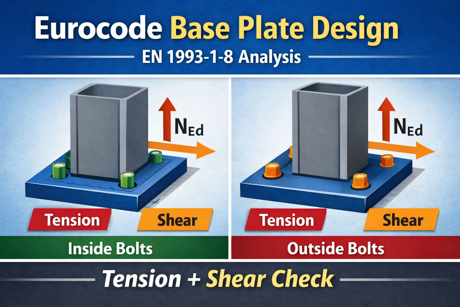
- Combined tension+shear interaction
You can also visualize bolt layouts for inside or outside column positions, helping engineers check proper spacing and edge distances.
Eurocode Base Plate Calculator – EN 1993-1-8
| Input Parameters | |
|---|---|
| Design Axial Load NEd (kN) | |
| Design Moment MEd (kNm) | |
| Design Shear Load VEd (kN) | |
| Base Plate Width Bp (mm) | |
| Base Plate Length Lp (mm) | |
| Concrete Strength fck (MPa) | |
| Plate Yield Strength fy (MPa) | |
| Number of Anchor Bolts | |
| Bolt Diameter (mm) | |
| Bolt Ultimate Strength fub (MPa) | |
| Edge Distance / Lever Arm e (mm) | |
| Bolt Position | |
| Column Width (mm) | |
| Column Length (mm) | |
How to Use This Eurocode Base Plate Calculator
- Enter the design axial load N in kN.
- Enter the design bending moment M in kNm.
- Enter the design shear load V in kN.
- Specify the base plate dimensions B
- Input concrete strength f and plate yield strength
- Enter number of anchor bolts and bolt diameter & strength.
- Choose bolt position – inside or outside column.
- Enter column size (width × length).
- The tool automatically calculates plate thickness, bolt tension, shear, and combined check.
- Visual representation of the plate, column, and bolt positions is generated for verification.
Detailed Calculation Steps
- Base Plate Area
Ap=Bp×Lp
- Concrete Bearing Pressure
σEd=ApNEd+BpLp26MEd
Allowable stress:σRd=γc0.85fck(γc=1.5)
- Plate Thickness
tp=fy/γM06Mpl,Ed(γM0=1.0)
- Bolt Tension
Nbolt,Ed=n⋅zMEd(z=lever arm based on bolt position)
- Bolt Shear
Vbolt,Ed=nVEd
- Bolt Capacities
As=4πd2 Nbolt,Rd=γM20.9AsfubVbolt,Rd=γM20.6Asfub(γM2=1.25)
- Combined Check (Eurocode Interaction)
Nbolt,RdNbolt,Ed+Vbolt,RdVbolt,Ed≤1
Notes:
- Inside column bolts are positioned within the column footprint for reduced lever arm.
- Outside column bolts are positioned near plate corners for maximum lever arm.
- Adjust bolt number, diameter, or position if combined check >1.
Why This Tool Helps Engineers
- Quick Eurocode-compliant calculation for base plates
- Clear visual verification of bolt placement
- Step-by-step calculation with references for documentation
- Supports both tension and shear combined checks
- Catch Basin Types and Details
 Catch basins are essential components of stormwater management systems. They… Read more: Catch Basin Types and Details
 - Eurocode Base Plate Calculator – EN 1993-1-8
 Introduction Base plates are critical components in steel structures, transferring… Read more: Eurocode Base Plate Calculator – EN 1993-1-8
 - Base Plate Design Calculation AS 4100
 Introduction In structural steel design, the base plate is a… Read more: Base Plate Design Calculation AS 4100
 - Base Plate Design Calculator CSA A23.3
 Introduction Steel column base plates transfer loads from the column… Read more: Base Plate Design Calculator CSA A23.3
 - Base Plate Design Calculator ACI 318
 Introduction Designing a steel column base plate is a critical… Read more: Base Plate Design Calculator ACI 318
 - Base Plate Design as per IS 800 2007
 Introduction (Anchor Bolts Outside & Inside Column Flange) Base plates… Read more: Base Plate Design as per IS 800 2007
 - East Facing 38×56 House Plan – Ground & First Floor Design with 3BHK + Home Theatre
 An east-facing house is considered highly auspicious in Vastu Shastra,… Read more: East Facing 38×56 House Plan – Ground & First Floor Design with 3BHK + Home Theatre
 - Foundation Detail Drawings for Buildings With CAD Files
 A Practical Structural Drawing Guide Introduction Footing drawings form the… Read more: Foundation Detail Drawings for Buildings With CAD Files
 - Bar Bending Schedule | BBS Calculator For Beam Column and Slab
 Managing the Bar Bending Schedule (BBS) is one of the… Read more: Bar Bending Schedule | BBS Calculator For Beam Column and Slab
 - Room Paint Calculator | Paint, Primer & Putty Quantity & Cost Estimator
 Looking to renovate your room? Our Room Paint, Primer &… Read more: Room Paint Calculator | Paint, Primer & Putty Quantity & Cost Estimator
 - Load Conversion & Stress Calculator | kN to kg, ton, N, MPa Online
 Load Conversion & Stress Calculator for Civil and Structural Engineers… Read more: Load Conversion & Stress Calculator | kN to kg, ton, N, MPa Online
 - Water Tank Capacity Calculator – Feet & Meter Conversion (Litres & Gallons)
 Water Tank Capacity Calculator with Unit Conversion Accurate water storage… Read more: Water Tank Capacity Calculator – Feet & Meter Conversion (Litres & Gallons)
 - Brick Wall Construction Calculator | Calculate Bricks & Cost Instantly |
 Introduction Building a brick wall requires accurate planning to avoid… Read more: Brick Wall Construction Calculator | Calculate Bricks & Cost Instantly |
 - Unit Converter – Feet, Inches, cm, mm, Yard to Meter and Vice Versa
 Length Unit Converter 🌙 Toggle Dark Mode Length Unit Converter… Read more: Unit Converter – Feet, Inches, cm, mm, Yard to Meter and Vice Versa
 - Lifting Analysis of Skid Using Spreader Beam 4-Point
 COG Shift, Moment Calculation & Sling Forces for STAAD Pro… Read more: Lifting Analysis of Skid Using Spreader Beam 4-Point
Related Posts:
Leave a Reply