
Introducing Steel Chimneys or Stack
The behavior of steel chimneys under dynamic loadings, such as wind, seismic activity, and vortex shedding, is a complex subject that involves understanding how these slender structures respond to time-varying forces. Steel chimneys are tall, narrow structures that are particularly susceptible to dynamic effects due to their height and slenderness. Here’s an overview of how they behave under different types of dynamic loadings:
1. Wind Loadings
- Gust Response: Steel chimneys are sensitive to wind gusts, which can induce oscillations. The dynamic response to wind loads includes both along-wind and across-wind responses.
- Vortex Shedding: When wind flows past a cylindrical structure like a chimney, it can create alternating low-pressure vortices on either side, leading to crosswind oscillations. This phenomenon can cause resonance if the frequency of vortex shedding matches the natural frequency of the chimney.
- Dynamic Amplification: The response of a steel chimney to wind loads can be amplified if the structure’s natural frequency is close to the frequency of the wind-induced forces, potentially leading to large displacements and stresses.
2. Seismic Loadings
- Base Shear and Overturning Moment: During an earthquake, the ground motion induces horizontal forces at the base of the chimney, generating base shear and overturning moments. These forces are critical in the design, as they can lead to significant stresses in the structure.
- Dynamic Analysis: The response of a steel chimney to seismic loads is typically analyzed using modal analysis or time-history analysis. These methods help predict the behavior of the structure under various seismic scenarios.
- Ductility and Energy Dissipation: Steel chimneys are designed to absorb and dissipate energy through ductile behavior, preventing brittle failure under seismic loading. The flexibility of steel allows for some degree of energy dissipation.
3. Vortex-Induced Vibrations (VIV)
- Resonance Effects: As mentioned earlier, vortex shedding can lead to resonance in steel chimneys if the shedding frequency aligns with the natural frequency of the structure. This can cause large-amplitude oscillations, leading to fatigue damage over time.
- Mitigation Strategies: To reduce VIV effects, design strategies such as altering the chimney’s shape, adding helical strakes, or installing tuned mass dampers are employed to either disrupt vortex formation or shift the natural frequency.
4. Fatigue Due to Cyclic Loading
- Cyclic Stresses: Repeated dynamic loadings, such as those caused by wind or seismic events, can induce cyclic stresses in the steel structure. Over time, these cyclic stresses can lead to fatigue, reducing the chimney’s lifespan.
- Fatigue Analysis: The analysis of fatigue involves understanding the number of load cycles and the stress range to predict when cracks might initiate and propagate.
5. Structural Damping and Energy Dissipation
- Material Damping: Steel has inherent material damping, but in tall, slender chimneys, additional damping mechanisms are often required to control dynamic response.
- Dampers: Tuned mass dampers (TMDs) or other energy-dissipation devices can be installed to reduce dynamic vibrations by absorbing energy and shifting the natural frequency away from resonant conditions.
6. Impact of Temperature and Thermal Loads
- Thermal Stresses: Dynamic loading can be exacerbated by temperature variations, which cause thermal expansion or contraction. Steel chimneys often experience significant temperature gradients due to their exposure to both the internal hot gases and the external environment.
- Thermal Fatigue: Repeated temperature cycles can induce thermal fatigue, especially when combined with mechanical dynamic loads.
7. Design Considerations for Dynamic Loadings
- Natural Frequency and Mode Shapes: The natural frequency and mode shapes of the chimney are crucial in determining its dynamic response. These parameters should be carefully analyzed and controlled during the design phase.
- Material Selection: The selection of steel grade and cross-sectional dimensions is essential to ensure the chimney can withstand dynamic loads without excessive deflection or stress concentration.
- Foundation Design: The dynamic response of the chimney is also influenced by the foundation design, which must provide adequate stiffness and damping to mitigate seismic and wind effects.
CHAPTER 1
INTRODUCTION
1.1 GENERAL
Chimneys or stacks are very important industrial structures for emission of poisonous gases to a higher elevation such that the gases do not contaminate surrounding atmosphere. These structures are tall, slender and generally with circular cross-sections. Different construction materials, such as concrete, steel or masonry, are used to build chimneys and tall industrial power plants structures. Steel chimneys are ideally suited for process work where a short heat-up period and low thermal capacity are required. Steel stack experience various loads in vertical and lateral directions. Important loads that a steel chimney often experiences are wind loads, earthquake loads, and temperature loads apart from self-weight, loads from the attachments, imposed loads on the service platforms. Wind effects on chimney plays an important role on its safety as steel chimneys are generally very tall structures.
The circular cross section of the chimney subjects to aerodynamic lift under wind load. Again seismic load is a major consideration for chimney as it is consider as natural load. This load is normally dynamic in nature. According to code provision quasi-static methods are used for evaluation of this load and recommend amplification of the normalized response of the chimney with a factor that depending on the soil and intensity of earthquake. In majority of the cases flue gases with very high temperature released inside a chimney. Due to this a temperature gradient with respect to ambient temperature outside is developed and hence caused for stresses in the cell. Therefore, temperature effects are also important factor to be considered in the steel design of chimney.
This chapter describes the wind load and seismic load effects on steel chimney there are many standards available for designing industrial steel chimneys. Geometry of a steel stack chimney plays an important role in its structural behaviour under lateral dynamic loading. This is because geometry is primarily responsible for the stiffness parameters of the chimney see Fig.1.1. However, the basic geometrical parameters of the steel chimney (e.g., overall height, diameter at exit, etc.) are associated with the corresponding environmental conditions. On top of that design code IS-6533: 1989 Part 2 imposes several criteria on the geometry of steel chimneys to ensure a desired failure mode. Two important IS-6533: 1989 recommended geometry limitations for designing steel stack are as follows:
- Minimum outside diameter of the unlined chimney at the top should be one twentieth of the height of the cylindrical portion of the chimney.
- Minimum outside diameter of the unlined flared chimney at the base should be 1.6 times the outside diameter of the chimney at top.
Present study attempts to justify these limitations imposed by the deign codes through finite element analyses of steel chimneys with various geometrical configurations.

Figure 1.1 Industrial structures for emission of poisonous gases
1.2 OBJECTIVE
- To find the behaviour steel stack under dynamic condition.
- Explore the values form ANSYS when shell with openings and compare with manual calculation.
1.3 SCOPE
- To justify the importance of geometrical limitations in the design of steel chimney.
- To explore the relation between geometrical parameters and corresponding stress values developed by using software and conventional method.
1.4 METHODOLOGY
To achieve the above objective following step-by-step procedures given in Fig.1.2 are followed:
Analyse all the chimney models using manual calculations (EXCEL) and finite element analysis (ANSYS).
CHAPTER 2
Figure 1.2 Step procedure flow chart
CHAPTER 2
LITERATURE REVIEW
2.1 GENERAL
A literature review is carried out on the design and analysis of steel chimney with special interest on the geometrical limitations. Although a number of literatures are available on the design and analysis of steel chimney there are only two published literature found that deals with the geometrical aspects of steel chimney. This section presents a brief report on the literatures reviewed as part of this project.
2.2 STUDIES REGARDING BEHAVIOUR OF STEEL STACK
Klein et. al. (2000) analysed the slim structures such as columns and chimneys, their dynamic behaviour has to be taken into account in calculating their dimensions. When exposed to wind, steel structures are particularly susceptible to vibrations because of their low damping. The results show that the influences the natural modes and natural periods of the chimney by considerable margin in design of stack.
Menon and Rao (1997) reviews the international code procedures to evaluate the across wind response of RC chimneys. The disparities in the codal estimates of across wind moments as well as the load factor specifications are examined in this paper through reliability approach. This paper recommends that it is necessary to design for the across wind loading at certain conditions.
Chmielewski, et. al. (2005) studied about natural frequencies and natural modes of 250 m highmulti-flue industrial RC chimney with the flexibility of soil. This paper used finite element method for analysis. Also, experimental work to investigate the free vibration response is carried out by using two geophone sensors and experimental results are compared with analytical results. The results show that the soil flexibility under the foundation influences the natural modes and natural periods of the chimney by considerable margin.
Flaga and Lipecki (2010) analysed the lateral response of steel and concrete chimneys of circular cross-sections due to vortex excitation. A mathematical model of vortex shedding is proposed for calculating maximum displacement of the chimney at top due to vortex shedding.
Galemann and Ruscheweyh (1992) presented the experimental work on measurements of wind induced vibrations of a steel chimney. For the along-wind vibration, the aerodynamic admission function has been developed from the vertical coherence of the wind speed as well as from the dynamic response directly. It is shown that the interaction effect between the strouhal frequency and the natural frequency of the chimney should produce a new exciting frequency which is lower than the strouhal frequency.
Hirsch and Ruscheweyh (1975) also analysed a steel chimney which is collapsed due to windinduced vibrations. The analysis considered cross-wind oscillations of steel stacks of given structural data (such as natural frequencies and log decrements). Hydraulic automotive shockabsorber to prevent vortex-induced oscillations is also demonstrated in this paper.
Kareem and Hseih (1986) carried out the reliability analysis of concrete chimneys under wind loading. In this paper, safety criteria are taken into consideration. Excessive deflection at the top of the chimney and exceedence of the ultimate moment capacity of the chimney cross-section at any level were taken as failure criterion. Formulation for wind-induced load effects, in the both along-wind and across-wind directions, is presented according to the probabilistic structural dynamics. Covariance integration method is used to formulate a special description of fluctuating wind load effects on chimneys. Load effects and structural resistance parameters are treated as random variables. These random variables are divided into three categories such as, wind environment and meteorological data, parameters reflecting wind-structure interactions and structural properties.
Kawecki and Zuranski (2007) measured the damping properties of the steel chimney due to cross-wind vibrations and also compared different approaches to the calculation of relative amplitude of vibration at small scruton number. They also gave importance to climatic conditions during vibrations. They also presented better description of cross-wind vibrationsaccording to the Eurocode and CICIND model code.
Pallares, et. al. (2006) discusses about the seismic behaviour of an unreinforced masonry chimney. A 3D finite element non-linear analysis is carried out incorporating cracking and crushing phenomena to obtain lateral displacements, crack pattern and failure mode. Also the maximum earthquake in terms of peak ground motion that the chimney can withstand is obtained.
Verboom and Koten (2010) shows that the design rules for cross-wind vibrations for steel chimney given by DIN 4133 and CICIND model code can differ by a factor 6 or more in terms of stress. Chimneys are modelled according to the Vickery-Basu model. This paper formulates adesign rule that computes more accurately the stresses in industrial chimneys due to vortex excitation.
2.2 SUMMARY
The literature review presented above shows that there are a number of published work on steel and concrete chimneys. Experimental and theoretical studies are presented on the behaviour of tall chimneys subjected to wind and seismic force. It is found that majority of the research papers on chimney are concentrated on its response to vortex shedding. However, a very less research effort is found on the geometric limitations of the design code with regard to steel chimneys.
CHAPTER 3
LOAD EFFECTS ON STEEL CHIMNEY
3.1 OVERVIEW
Steel chimneys experience various loads in vertical and lateral directions. Important loads that a steel chimney often experiences are wind loads, earthquake loads, and temperature loads apart from self-weight, loads from the attachments, imposed loads on the service platforms. Wind effects on chimney plays an important role on its safety as steel chimneys are generally very tall structures. The circular cross section of the chimney subjects to aerodynamic lift under wind load. This load is normally dynamic in nature. Due to this a temperature gradient with respect to ambient temperature outside is developed and hence caused for stresses in the cell. Therefore, temperature effects are also important factor to be considered in the steel design of chimney.
3.2 WIND ENGINEERING
For steel chimney, wind is considered as major source of loads. This load can be divided into two components respectively such as,
- Along-wind effect
- Across -wind effect
The wind load exerted at any point on a chimney can be considered as the sum of quasi-static and a dynamic-load component. The static-load component is that force which wind will exert if it blows at a mean (time-average) steady speed and which will tend to produce a steady displacement in a structure. The dynamic component, which can cause oscillations of a structure, is generated due to the following reasons:
-
- Gusts
- Vortex shedding
- Buffeting
3.2.1 Along Wind Effects
Along wind effects are happened by the drag component of the wind force on the chimney. When wind flows on the face of the structure, a direct buffeting action is produced. To estimate such type of loads it is required to model the chimney as a cantilever, fixed to the ground. In this model the wind load is acting on the exposed face of the chimney to create predominant moments. But there is a problem that wind does not blow at a fixed rate always. So the corresponding loads should be dynamic in nature. For evaluation of along wind loads the chimney is modelled as bluff body with turbulent wind flow.
3.2.2 Across Wind Effects
Across wind effect is not fully solved and it is required a considerable research work on it. For design of steel chimney, Indian standard remain silent about it. But it is mentioned in IS 4998 (part 1): 1992 and ACI 307-95 which is applicable for concrete chimney only. Also CICIND code does not mention this effects and depends on IS 4998 (part 1): 1992 and ACI 307-95.Generally chimney-like tall structures are considered as bluff body and oppose to a streamlines one. When the streamlined body causes the oncoming wind flow, the bluff body causes the wind to separate from the body. These vortices alternatively forms lift forces and it acts in a direction Perpendicular to the incident wind direction. Chimney oscillates in a direct ion perpendicular to the wind flow due to this lift forces.
3.3 WIND LOAD CALCULATION
In many codes including IS: 6533:1989, equivalent static method is used for estimating these loads. In this procedure the wind pressure is determined which acts on the face of the chimney as a static wind load. Then it is amplified using gust factor to calculate the dynamic effects. According to IS-875:1987 part-3 basic wind speed can be calculated,
Vz =Vb K1 K2 K3 (3.1)
where,
Vz= design wind speed at any height z (m/s)
Vb= basic wind speed (m/s)
K1= probability factor (risk coefficient)
K2= terrain, height and structure size factor
K3= topography factor
3.4 STATIC WIND EFFECTS
A static force called as drag force, obstructs an air stream on a bluff body like chimney. The distribution of wind pressure depends upon the shape and direction of wind incidence static wind effects are drag and circumferential bending..
3.4.1 Drag
The value of drag coefficient depends on Reynolds number, shape and aspect ratio of a structure. Drag force creates along-wind shear forces and bending moments. The drag force on a single stationary bluff body is,
F = 1 Cd A ρa U2 (3.2)
2
where,
Fd = drag force, (N)
Cd = Drag coefficient
A = area of section normal to wind direction, sq. m
3.4.2 Circumferential Bending
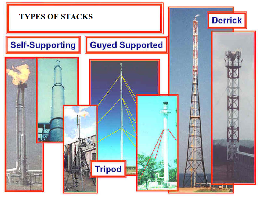
Due to this a circumferential bending occurs and it is more significant for larger diameter chimney.. The radial distribution of wind pressure on horizontal section depends on Reynolds number. Normally the resultant force of along wind is counteracted by shear force s which is induced in the structure. These shear forces are assumed to vary along the circumference of the chimney cell. Steel stacks are in four types they are adopting based on the industrial power plants and their requirement in Fig.3.1 here we are choosing self-supported steel stack for our study.
3.4.3 Wind Load on Liners
In both single-flue and multi-flue chimneys metal liners are being used but these are not direct contact or exposed to wind. But they are designed for wind loads which are transmitted through the chimney cell.
Figure 3.1 Types of steel chimneys
The magnitude of the force can be estimated by considering the liner as a beam of varying moment of inertia, acted upon by a transverse load at the top and deflection is calculated at the top of the cell.
3.5 DYNAMIC WIND EFFECTS
If the period of natural oscillation for the chimney computed as given below exceeds 0.25 seconds, the design wind loads shall take into consideration the dynamic effect due to pulsation of thrust caused by wind velocity in addition to the static wind load calculated under IS-6533 clause 8.2.3.
Dynamic effect of wind is influenced by a number of factors, such as, mass and its disposition along chimney height, period and mode of natural oscillation. 1ogarithmic decrement of dampening, pulsation of velocity thrust, etc. Values of dynamic components of wind load should be determined for each mode of oscillation of the chimney as a system of inertia forces acting at the centre of the zone being considered.
3.6 SEISMIC EFFECTS
Due to seismic action, an additional load is acted on the chimney. It is considered as vulnerable because chimney is tall and slender structure. Seismic force is estimated as cyclic in nature for a short period of time. When chimney subjected to cyclic loading, the friction with air, friction between the particles which construct the structure, friction at the junctions of structural elements, yielding of the structural elements decrease the amplitude of motion of a vibrating structure and reduce to normal with corresponding to time.. For analysis purpose, chimney is behaved like a cantilever beam with flexural deformations.
Analysis is carried out by following one of the methods according to the IS codal provision,
- Response-spectrum method (first mode)
- Modal-analysis technique (using response spectrum)
- Time-history response analysis.
3.6.1 Response Spectrum Method
For designing earthquake resistant structures, it is necessary to evaluate the structural response to ground motion and calculate respective shear force, bending moments. Hence ground motion is the important factor for seismic evaluation. This method consists of three steps such as,
- Fundamental period
- Horizontal seismic force
- Determine design shears and moments
The fundamental period of the free vibration is calculated as,
T = Ct Wth 1/2 (3.3)
EsAg
where
Ct = coefficient depending on slenderness ratio of the structure
W t= total weight of the structure including weight of lining and contents above the base,
A = area of cross-section at the base of the structural shell
h = height of the structure above the base
Es= modulus of elasticity of material of the structural shell
g= acceleration due to gravity
Stiffness of the flared chimney is approximately two times the prismatic chimney. Therefore the conservative estimate of natural time period for this steel chimney will be the horizontal seismic force (Ah) is to be calculated according to IS-1893 (Part 1): 2002 as follows:
Ah= Z Sa I (3.4)
2 g R
where,
Z= zone factor
I= importance factor
R= response reduction factor. The ratio shall not be less than 1.0
Sa/g= spectral acceleration coefficient for rock and soil site
3.7 SUMMARY
This Chapter presents the effects of wind and seismic load on self-supporting steel chimneys. It also describes briefly the procedures to calculate static wind, dynamic wind and seismic force as per Indian Standard IS 6533 (Part-2):1989.
CHAPTER 4
DESIGN OF STEEL CHIMNEY
4.1 OVERVIEW
This chapter presents procedures to design self-supported steel chimney as per IS-6533:1989 part 1&2 through an example calculation. A typical chimney to be located at Assam for an exit flue discharge of 100000 m3/s is taken for the example. The chimney is first designed for static wind load and then the design is checked against dynamic wind load, possible resonance and seismic load.
4.2 DESIGN ASPECTS OF STEEL CHIMNEY
This part covers design, construction maintenance and inspection of steel stacks. Two aspects are considered for steel stack analysis and design they are:
- Mechanical aspects
- Structural aspects
4.2.1 Mechanical Aspects
This also includes lining materials, draft calculations, consideration for dispersion of pollutants into atmosphere and ash disposal. It can be exhaust a given quantity of flue gases at a suitable elevation and with such a velocity that the Ground Level Concentration (GLC) of pollutants, after atmospheric dispersion, is within the limits prescribed in pollution regulatory standards, while the stack retains structural integrity, According to code provision quasi-static methods are used for evaluation of this load and recommend amplification of the normalized response of the chimney with a factor that depending on the soil and intensity of earthquake the major factors which influence a stack dimensions are:
- Draft requirements
- Environmental regulations
- Structural considerations
Compositions of flue gas are specific weight, quantity of dust data above the aggressiveness of gases. In order to minimize loss of heat from a stack and to maintain the temperature of the steel shell above the acid due point level external insulations may be fitted. The amount of insulation required to maintain the temperature of flue gases above he acid dew point depends upon:
- Effective of insulation
- Te velocity of the gases
- The inlet temperature of the flue gases
According to code IS-14164:2008, industrial application and finishing’s of thermal insulation materials at temperatures above -800 C and up to 7500 C, code of practice deals with the material selection for selection for insulation and method of application.
4.2.2 Structural Aspects
It covers loadings, load combinations, materials of construction, inspection, maintenance and painting of both steel stack and guyed steel stacks (with or without lining) and there supporting structures.
4.3 APPLICABLE CODES FOR DESIGN
Code of practice for design loads other than earthquake for buildings and structures (wind loads). IS: 875 (Part-3) was adopted by bureau of Indian Standards after the draft finalized by the structural safety sectional committee had been approved by the civil engineering division council. This part covers
-
- Wind loads to be considered when designing buildings, structures and components.
- It gives the basic wind speeds for various locations in India.
- Factors to be considered while estimating the design wind speed/pressure.
Indian standard design and construction of steel stacks-code of practice (Mechanical aspects) IS-6533:1989 (Part-1). This includes
- Determination of top to base diameter.
- Determination of stack height based on pollution norms and dispersion of gases into the atmosphere.
- General requirements for materials of construction, insulation, lining and cladding.
This is Code of practice for design and construction of steel chimneys (structural aspect)IS-6533:1989 (Part-2). This includes
- Material of construction for bolts, plates, rivets and welding
- Loadings and load combinations
- General design aspects covering minimum thickness of shell. Allowable stresses, allowable deflection, determination of dynamic force and checking for resonance.
- Typical ladder details, painters trolley, location of warning lamps and the flue opening details, inspection, maintenance and protective coatings.
4.3.1 Assumptions
The assumptions that carried out for analysis and design are given below:
-
- The wind pressure varies with the height. It is zero at the ground and increase as the height. For the purpose of design it is assumed the wind pressure is uniform throughout the height of the structure.
- For the purpose of calculations, it is assumed that the static wind load (projected area multiplied by the wind pressure) is acting at the centre of pressure.
- The base of the stack is perfectly rigid and the effect of the gussets and stool plate on the deflection and the stresses in the stack is not considered. This is applicable only for manual calculations.
- Earthquake causes impulsive ground motions, which are complex and irregular in character, changing in period and amplitude each lasting for a small duration.
4.4 LOADINGS AND LOAD COMBINATIONS
Steel stack experience various loads in vertical and lateral directions. Important loads apart from dead load that a steel chimney often experiences the below given loads are to be estimated while designing the steel chimney.
a. Wind load
b. Earthquake load
c. Imposed load
4.4.1 Load Combinations
As per IS: 6533 (Part 2), the following load causes are to be considered while designing the stack.
a. Load case 1 = Dead load + wind load (X direction) + Imposed load
b. Load case 2 = Dead load + wind load (Y direction) + Imposed load
c. Load case 3 = Dead load + Imposed load + earthquake load
4.5 SAMPLE DESIGN CALCULATIONS
When designing chimneys, their dynamic behavior has to be taken into account in calculating their dimensions. When exposed to wind, steel structures are particularly susceptible to vibrations because of their low damping. Based on the calculated loads the structural design as follows.
4.5.1 Design Inputs
Following are the inputs and materials used to analyse and design the chimney.
Diameter of the Stack : 4.4 m
Height of Stack : 40 m
Basic Wind Speed : 47 m / sec
Coefficients for calculating Wind Loads: (as per IS 875)
- Risk Coefficient, k1 factor : 1.08
- Terrain, Height and Structure Size Factor, k2 : Ref Table 2 of IS 875
- Topography (k3 factor) : 1As per IS 875: 1987 (Table – 2)
- Terrain Category -1 : A
- Class : B

Figure 4.1 Base plan of chimney
The top to base dimension is most important one for defining the chimney in Fig.4.1 the base plan given with top to base as the same diameter. The Earth Quake Loads have been calculated as per IS 1893 – 2002 for the structure under consideration, the following values have been assumed for the various parameters mentioned above.
Z = 0.24 (Zone IV of IS 1893)
I = 1.5 (As per Table 6 of IS 1893)
R = 5 (As per Table 7 of IS 1893)
4.5.2 Materials
The following are the materials which are used for chimney construction:
All Structural Steel to conform to : IS 2062: 1984, fy = 250 Mpa
Bolts (property class 4.6) to conform to : IS 6639: 1972
Nuts shall conform to : IS 1363 (part 3): 1984
Washers shall conform to : IS 2016: 1967
Heavy Washers shall conform to : IS 6610
Spring Washers shall conform to : IS 3063
Design shall conform to : IS 6533: 1984 (Part 2) 1989
Permissible Stresses in Bolts:
- Perm Shear Stress on Gross c/s Area of Bolt, s
: 80 N / mm2
- Perm Axial Tensile Stress on Net c/s Area of Bolt, a : 120 N / mm2
4.5.3 Static Wind Force Calculation
When wind flows on the face of the structure, a direct buffeting action is produced. To estimate such type of loads it is required to model the chimney as a cantilever, fixed to the ground. In this model the wind load is acting on the exposed face of the chimney to create predominant moments For computing wind loads and design of chimney the total height of the is divided into 4 parts of height variations Parts: 35m to 40m, 25m to 35m, 15m to 25m, and 0 to 15m.
Basic wind speed : 47 m/s
For Terrain Category A and Class B Structure, k1
: 1.07
Topography (k3 factor) : 1
As per IS: 6533 Part 2 C : 0.7for circular section
For computing wind loads the Terrain, Height and Structure Size Factor, K2 is required base on height variation the value is computed and given below in Table 4.1 as per IS 875
Table 4.1 Factor k2 at various heights
| S.No | Ht (m) | k2 |
| 1. | 10 | 1.03 |
| 2. | 15 | 1.07 |
| 3. | 20 | 1.10 |
| 4. | 30 | 1.13 |
| 5. | 50 | 1.18 |
Table 4.2 Moment due to static wind
| Ht at topof panel | Ht at bottomof panel | k2 | Wind presskg/m2 | WF acting at | Dia whereforce acts | WFKg | Mwind tmat base | |
| S.No | ||||||||
| 1. | 40.00 | 37.500 | 1.155 | 206.4 | 38.750 | 4.400 | 1589.4 | 61.589 |
| 2. | 37.50 | 35.000 | 1.149 | 204.2 | 36.250 | 4.400 | 1572.2 | 56.994 |
| 3. | 35.00 | 32.500 | 1.143 | 202.0 | 33.750 | 4.400 | 1555.2 | 52.487 |
| 4. | 32.50 | 30.000 | 1.136 | 199.8 | 31.250 | 4.400 | 1538.2 | 48.069 |
| 5. | 30.00 | 27.500 | 1.130 | 197.6 | 28.750 | 4.400 | 1521.3 | 43.738 |
| 6. | 27.50 | 25.000 | 1.123 | 195.0 | 26.250 | 4.400 | 1501.2 | 39.407 |
| 7. | 25.00 | 22.500 | 1.115 | 192.4 | 23.750 | 4.400 | 1481.2 | 35.179 |
| 8. | 22.50 | 20.000 | 1.108 | 189.8 | 21.250 | 4.400 | 1461.4 | 31.054 |
| 9. | 20.00 | 17.500 | 1.100 | 187.2 | 18.750 | 4.400 | 1441.6 | 27.031 |
| 10. | 17.50 | 15.000 | 1.085 | 182.2 | 16.250 | 4.400 | 1402.6 | 22.792 |
| 11. | 15.00 | 12.500 | 1.070 | 177.2 | 13.750 | 4.400 | 1364.1 | 18.756 |
| 12. | 12.50 | 10.000 | 1.050 | 170.6 | 11.250 | 4.400 | 1313.6 | 14.777 |
| 13. | 10.00 | 7.500 | 1.030 | 164.2 | 8.750 | 4.400 | 1264.0 | 11.060 |
| 14. | 7.50 | 5.000 | 1.030 | 164.2 | 6.250 | 4.400 | 1264.0 | 7.900 |
| 15. | 5.00 | 2.510 | 1.030 | 164.2 | 3.755 | 4.400 | 1258.9 | 4.727 |
| 16. | 2.51 | 0.000 | 1.030 | 164.2 | 1.255 | 4.400 | 1269.0 | 1.593 |
| 0.00 | 22.80 | 477.154 |
The wind load is acting on the exposed face of the chimney to create predominant moments for computing wind loads moments and design of chimney the total various heights are calculated in the given below Table 4.2.
Average wind pressure up to 10 m : 0.164 T/m2
Average wind pressure 10 – 20 m : 0.176 T/m2
Average wind pressure 20 – 30 m : 0.192 T/m2
Average wind pressure 30 – 40 m : 0.202 T/m2
Average wind pressure 40 to top : 0.206 T/m2
Table 4.3 Total weight of chimney
| S.No | Height (m) | Outer Dia (m) | Thk (mm) | Mean Dia (m) | Area | Volume upto h (m3) | Lumped wt (t) |
| 1. | 0 | 4.4 | 20.00 | 4.380 | 0.275 | 0.69 | 10.802 |
| 2. | 2.50 | 4.400 | 20.00 | 4.380 | 0.275 | 0.69 | |
| 3. | 5.00 | 4.400 | 20.00 | 4.380 | 0.275 | 0.69 | 10.802 |
| 4. | 7.50 | 4.400 | 20.00 | 4.380 | 0.275 | 0.69 | |
| 5. | 10.00 | 4.400 | 20.00 | 4.380 | 0.275 | 0.69 | 10.802 |
| 6. | 12.50 | 4.400 | 20.00 | 4.380 | 0.275 | 0.69 | |
| 7. | 15.00 | 4.400 | 20.00 | 4.380 | 0.275 | 0.69 | 10.802 |
| 8. | 17.50 | 4.400 | 20.00 | 4.380 | 0.275 | 0.69 | |
| 9. | 20 | 4.400 | 20.00 | 4.380 | 0.275 | 0.69 | 10.802 |
| 10. | 22.5 | 4.400 | 20.00 | 4.380 | 0.275 | 0.69 | |
| 11. | 25 | 4.400 | 20.00 | 4.380 | 0.275 | 0.69 | 10.802 |
| 12. | 27.5 | 4.400 | 20.00 | 4.380 | 0.275 | 0.69 | |
| 13. | 30 | 4.400 | 20.00 | 4.380 | 0.275 | 0.69 | 10.802 |
| 14. | 32.5 | 4.400 | 20.00 | 4.380 | 0.275 | 0.69 | |
| 15. | 35 | 4.40 | 20.00 | 4.380 | 0.275 | 0.69 | 10.802 |
| 16. | 37.5 | 4.40 | 20.00 | 4.380 | 0.275 | 0.69 | |
| 17. | 40 | 4.40 | 20.00 | 4.380 | 0.275 | 0.69 | 5.401 |
| 10.32 | 86.414 |
Due to seismic action, an additional load is acted on the chimney. It is considered as vulnerable because chimney is tall and slender structure for the structure under dead load consideration. In the Table 4.3 total mass of the chimney is calculated for seismic lumped mass calculation and the values are given top to base at various heights.
4.6 SEISMIC BASE SHEAR CALCULATIONS
The Earth Quake Loads have been calculated as per IS 1893 – 2002 According to IS 1893, the horizontal seismic coefficient, Ah is given by
Ah = Z I Sa (3.1)
2 R g
where,
Z = Zone Factor taken from Table 2 of IS 1893
I = Importance Factor depending upon the functional use of the structure.
R = Response Reduction Factor taken from Table 7 of IS 1893
Sa / g = Average response acceleration coefficient.
Design data:
Height of tower : 40 m
Diameter at the base : 4.4 m
Thickness of shaft at base : 16 mm
Diameter at the top : 4.4 m
Thickness of shaft at start : 20 mm
Thickness of shaft at top : 20 mm
Density of steel : 7.85 T/m3
Time period : 0.09h/√d (3.2)
: 1.7sec > 0.1 sec
Z = 0.24 (Zone IV of IS 1893)
I = 1.5 (As per Table 6 of IS 1893)
R = 5 (As per Table 7 of IS 1893)
Sa/g = 0.79 (Medium soil – From – IS: 1893 – 2002)
Ah : 0.029
Total weight of stack including platform: 109.48 T
Base shear : 3.12 T
The design base shear is distributed along the height of the structure as per IS:1893 – 2002 Clause 7.7.1
Qi = Vb Wihi2 / SWihi2 (3.3)
where,
Vb = Base Shear due to seismic
Wi = Weight of the structure
Hi = height of the structure
Due to seismic action, an additional load is acted on the chimney. It is considered as vulnerable because chimney is tall and slender structure.
Table 4.4 Seismic shear at various levels on chimney
| S.No | Wi (t) | hi (m) | hi2 | Wihi2 | Qi |
| 1. | 10.80 | 0 | 0.00 | 0 | 0.000 |
| 2. | 10.80 | 5.00 | 25.00 | 270.04 | 0.022 |
| 3. | 10.80 | 10.00 | 100.00 | 1080.17 | 0.089 |
| 4. | 10.80 | 15.00 | 225.00 | 2430.39 | 0.201 |
| 5. | 10.80 | 20.00 | 400.00 | 4320.69 | 0.357 |
| 6. | 10.80 | 25.00 | 625.00 | 6751.08 | 0.558 |
| 7. | 10.80 | 30.00 | 900.00 | 9721.56 | 0.803 |
| 8. | 10.80 | 35.00 | 1225.00 | 13232.12 | 1.093 |
| 9. | 5.40 | 40.00 | 1600.00 | 8641.390 | 0.714 |
From the Table 4.4 based on the various stage of dead load the seismic shear and moment can be estimated. Seismic force is estimated as cyclic in nature for a short period of time to evaluate the structural response to ground motion and calculate respective shear force, bending moments. Hence ground motion is the important factor for seismic evaluation. The seismic moment at the base can be estimated as 87.4 Tm. To estimate exact future ground motion and its corresponding response of the structure, it depends on soil-structure interaction, structural stiffness, damping etc.
4.7 CALCULATION OF DYNAMIC WIND
If the period of natural oscillation for the chimney computed as given below exceeds 0.25 seconds, the design wind loads shall take into consideration the dynamic effect due to pulsation of thrust caused by wind velocity in addition to the static wind load calculated under IS-6533:1989 Clause 8.2.3. The dynamic component of wind load is determined for the first mode. (Note: Higher modes may be considered when the chimney is very tall (80m and above)
Here i = 1 since only the first mode is considered.
Pdyn,j = Mj i j (3.4)
where,
Mj – Mass of jth zone
i – Dynamic coefficient as per IS-6533:1989 Clause 8.3.3 determined for unlined chimneys as per Table 5 based on the value.
1 = Ti Vb/1200 : 0.012
For this value of 1, i (From Table 5) : 1.876
j = Yij Syik Pst,k mk
Sy2ik Mk
where,
j – Deduced acceleration in m/ sec2 as per Cl 8.3.4
Yik Yij – relative ordinate of the mode shape at the centre of the kth & jth zones respectively
mk – From Table 6 Coefficient of pulsation of speed thrust: 0.6 (For A type of location & height up to 40m)
Density of steel : 7.85T/m2
Since only one mode (first mode) is considered, the design lateral force, bending moment and deflections due to wind load should be computed by adding the static and dynamic components in Table 4.5 calculation of dynamic wind at various heights and based on these loads the moments are computed in the given Table 4.6. The predominant moment is based on the dynamic load 829.55Tm at base as per the Table 4.6.
Table 4.5 Dynamic wind loads on chimney
| S.No | Zone | Level z | Y | Dia at z | Thk (m) | Mass (T) | Yj | Yk | Y2k | p (T/m2) |
| 1. | 4 | 40 | 1.000 | 4.400 | 0.020 | 21.702 | 0.809 | 0.809 | 0.654 | 0.206 |
| 2. | 3 | 30 | 0.617 | 4.400 | 0.020 | 21.702 | 0.455 | 0.455 | 0.207 | 0.198 |
| 3. | 2 | 20 | 0.293 | 4.400 | 0.020 | 21.702 | 0.185 | 0.185 | 0.034 | 0.187 |
| 4. | 1 | 10 | 0.076 | 4.400 | 0.012 | 13.021 | 0.038 | 0.038 | 0.001 | 0.164 |
Table 4.6 Dynamic wind moments for various heights
| S.No | Pst (T) | YikPst,kmk | y2ik Mk | hj | Pdyn | PDesign | Load at | BM at base |
| 1. | 6.358 | 3.085 | 14.192 | 0.229 | 6.519 | 12.877 | 35.00 | 450.68 |
| 2. | 6.085 | 1.662 | 4.495 | 0.129 | 3.669 | 9.754 | 25.00 | 243.86 |
| 3. | 5.767 | 0.638 | 0.739 | 0.052 | 1.487 | 7.254 | 15.00 | 108.81 |
| 4. | 5.056 | 0.115 | 0.019 | 0.011 | 0.184 | 5.240 | 5.00 | 26.20 |
| 23.265 | 5.500 | 19.444 | 35.125 | 829.55 |
4.7.1 Check for Resonance
The chimney is first designed for static wind load and then the design is checked against dynamic wind load, possible resonance and seismic load. Check for resonance is to be carried out only if the above ratio is between 0.33 and 0.8. As per IS 6533 Part 2 the critical strouhal velocity.
Vcr = 5 Dt f (3.5)
where,
f – Natural frequency of the chimney : 3.244 Hz
Dt – Diameter of chimney at top : 4.400 m
Vcr : 71.4 m/s
Design wind velocity : 54.94 m/s Vcr/ Vd : 1.30
The natural frequency as per clause 8.3 : ½ p [g S (mx)/S (mx2)] 1/2 : 0.64
The mode shape is approximated by the following in the absence of software results, mode shapes can be obtained from the below expressions and the values are computed and tabulated in below Table 4.7. Design codes consider two modes of failure to arrive at the thickness of chimney shell material yielding in tension and compression and local buckling in compression in below profile 1&2 y is the various height of the chimney.
Profile 1 z = 1 – cos (py/2L)
Profile 2 z = (y/L) 2 (3/2 – y/2L)
Table 4.7 Mode shapes for various heights
| S.No | y | z Profile 1 | z Profile 2 |
| 1. | 0 | 0.0000 | 0.000 |
| 2. | 10 | 0.0761 | 0.086 |
| 3. | 20 | 0.2929 | 0.313 |
| 4. | 30 | 0.6173 | 0.633 |
| 5. | 40 | 1.0000 | 1.000 |
4.8 DESIGN OF SHELL THICKNESS
Based on the shell thickness the calculated stresses from the governing loading combinations of same thickness and geometrical parameters are used to carry out the results. The stress calculation is based on the shell thickness of chimney. The chimney will not exceed the allowable limits permitted by the applicable codes, standards, and specifications. The stress calculation is based on the shell thickness of chimney.
Weight of Shell P =
P = p x (Od – ts) x ts x 7.85 x hs x 1.4 (3.6)
where,
Od – outer diameter of stack
ts – Thickness of shell
The weight of the shell is multiplied by 1.4 to take care of the weight of Stiffeners and due to platform load at various levels of load can take care in the levels of 20m, 30m and 40m given in below Table 4.8
Table 4.8 Total vertical load on chimney
| S.No | Height Above G.L. (m) | Wt. Of Shell(Kg) | Load due to Platform(kg) |
| 1. | 0 – 2.5 | 5400.87 | – |
| 2. | 5 | 5400.87 | – |
| 3. | 7.5 | 5400.87 | – |
| 4. | 10 | 5400.87 | – |
| 5. | 12.5 | 5400.87 | |
| 6. | 15 | 5400.87 | – |
| 7. | 17.5 | 5400.87 | – |
| 8. | 20 | 5400.87 | 9225.73 |
| 9. | 22.5 | 5400.87 | – |
| 10. | 25 | 5400.87 | – |
| 11. | 27.5 | 5400.87 | – |
| 12. | 30 | 5400.87 | 4612.86 |
| 13. | 32.5 | 5400.87 | – |
| 14. | 35 | 5400.87 | – |
| 15. | 37.5 | 5400.87 | – |
| 16. | 40 | 5400.87 | 9225.73 |
| Total | 86413.90 | 23064.32 |
In Table 4.8 the total dead load of the structure are calculated for various heights of the chimney. The total mass of the structure are used for calculation of natural frequency of the stack. The opening at the level of 1.2m from the base considered the wind load calculation. The dynamic analysis is carried out and the total forces due to static force of moment can be tabulated in Table 4.9.
Table 4.9 Moments due to wind load
| S.No | Level(m) | Force(kg) | Lever arm(m) | Moment(kgm) |
| 1. | 2.5 | 1269.05 | 0.05 | 63.45 |
| 2. | 5 | 1258.93 | 2.55 | 3210.28 |
| 3. | 7.5 | 1263.99 | 5.05 | 6383.15 |
| 4. | 10 | 1263.99 | 7.55 | 9543.12 |
| 5. | 12.5 | 1313.55 | 10.05 | 13201.21 |
| 6. | 15 | 1364.07 | 13.75 | 18755.96 |
| 7. | 17.5 | 1402.58 | 15.05 | 21108.87 |
| 8. | 20 | 1874.12 | 17.55 | 32890.84 |
| 9. | 22.5 | 1603.70 | 20.05 | 32154.14 |
| 10. | 25 | 1625.49 | 22.55 | 36654.84 |
| 11. | 27.5 | 1647.43 | 26.25 | 43245.12 |
| 12. | 30 | 1977.74 | 28.75 | 56860.04 |
| 13. | 32.5 | 1688.04 | 31.25 | 52751.26 |
| 14. | 35 | 1706.66 | 33.75 | 57599.84 |
| 15. | 37.5 | 1725.39 | 36.25 | 62545.22 |
| 16. | 40 | 2066.22 | 38.75 | 80065.99 |
| Total | 25050.96 | 527033.33 |
Total Moment at the Opening Level, Mo: 527.0 Tm
4.8.1 Seismic Analysis
When this friction fully dissipates the structural energy during its motion, the structure is called critically damped. To estimate exact future ground motion and its corresponding response of the structure, it depends on soil-structure interaction, structural stiffness, damping etc based on the above calculation of the Seismic Analysis results are carried out as per IS1893. The shear due to Seismic load.
Shear due to seismic v : 3123.20 kgs
Total Moment at opening level Moe : 58716.2 kgm
4.8.2 Check for Shell Thickness
Manholes are generally provided at the bottom of the chimney for maintenance and inspection purpose. The standard dimension of any steel stack of manhole is 500 mm × 800 mm according to Indian standard IS 6533 (Part-2):1989 Check at the bottom of Opening Level the values are detailed calculation values are given below.
Total Vertical load due to shell and Platforms : 109478.2 kgs
Load due to Silencer and Expansion Joint : 9500.00 kgs
Total Vertical Load, P : 118978.2 kgs
Total Moment, M : 829548.1 kgm
Width of the Opening, Wo : 1200.0 mm
Angle subtended by opening at the Centre
Q = 2 x Sin-1(Wo/R) : 31.7 Degrees
Width of the Opening along the Circumference, Woc = Rq =1215 mm
Area of Cross section of the shell,
A = p x (Od2 – Id2)/4 – Woc x ts : 2134.21 cm2
Section Modulus, Zopening =
0.77 x Od2 x t x (1- 0.65 x Wo/Od) : 208497.52 cm3
Section Modulus without opening : 295439.80 cm3
Stress in Shell due to Vertical Loads = P/A : 51.3 kg/cm2
Stress in Shell due to Bending Moment = M/Z : 397.9 kg/cm2
Total Stress with opening : 449.2 kg/cm2
Total Stress without opening : 359.5 kg/cm2
Allowable deflection dall = L/200 : 20.0 cm
Deflection with opening : 2.081 cm
Deflection without opening : 1.458 cm
For calculating the actual deflection, the total shear due to wind load is applied as a uniformly distributed load throughout top to bottom of chimney.
4.8.3 Calculation of Allowable Stresses
Forthe calculation of shell thickness the design aspects covering the allowable stresses values are should be taken as per IS 6533 – (Part-2) mainly as per the temperature conditions,. And also the allowable stress value should be based on IS-800:1984. Due to circumferential bending occurs and it is more significant for larger diameter chimney. Also drag force creates along-wind shear forces and bending moments. The stress calculation is based on the shell thickness of chimney. For the Stack under consideration he/D : 8.8
And D/ts : 258.8
Allowable stress,
a = 0.5 x fy x A x B (Refer IS 6533) (3.7)
where,
fy – yield stress of steel
A = 1 if he/D < 21 if h/ D >21
For this case, A = 1
B = 270 x t/D x (1 – 67 x t/D) if D/t > 130
= 1 if D/t < 130
For this case, B = 0.773
a = 985.8 Kg/cm2
a = 985.8 Kg/cm2 > 449.2 kg/cm2 Hence Safe
The allowable stress is more than the actual stress. The convention method of calculation with manhole analysis gives results will not exceed the allowable limits permitted by the applicable codes, standards, and specifications. The stress calculation is based on the shell thickness of chimney
CHAPTER 5
EFFECT OF GEOMETRY ON THE DESIGN OF STEEL CHIMNEY
5.1 INTRODUCTION
This Chapter deals with the analysis of steel chimneys. The chimney is idealized as cantilever column with tubular cross section for analysis. As explained in the previous chapter the main loads to be considered during the analysis of chimneys are wind loads and seismic loads in addition to the dead loads. Basic dimensions of a self supporting steel chimney is generally obtained from the environmental consideration. Other important geometrical considerations are limited by design code IS 6533 (Part 1 & 2): 1989 to obtained preferred mode of failure Section discusses the geometry limitations recommended by IS 6533 (Part 1 & 2): 1989. This chapter attempts to assess these limitations through analysis of different chimney geometries. The top to base as same diameter without any variations used in this chimney geometry as considered for this study. Also, a study is carried out to understand the chimney behavior with inspection manhole at the lower end of the chimney. Last part of this chapter presents the difference of chimney behavior with and without the inspection manhole. Analysis is carried out through manual calculations using excel as well as finite element analysis using commercial software ANSYS.
The bending moment calculated on the base of the chimney for dynamic wind load as a function of top-to-base diameter ratio for different height-to-base diameter ratio. This shows that the base moment increases with the increase of top-to-base diameter ratio almost proportionally. That base moment increases with the increase of height-to-base diameter ratio. However, the rate of increase in base moment is slightly less for lower value of height-to-base diameter ratio. There is a sudden increase of the gradient of the base moment curve for height-to-base diameter ratio = 14. Maximum bending stresses in the chimney also calculated and presented in Fig. 5.3 and 5.4 for same and top-to-base diameter ratio. a typical chimney model It is clear from these figures that base moment (maximum moment) and the maximum bending stress due to dynamic wind load are continuous function of the geometry (height-to-base diameter ratio). Therefore this study support the limitations imposed by IS 6533 (Part-2): 1989 with regard to the selection of basic dimensions of self supporting steel chimneys.
5.2 EFFECT OF MANHOLE ON SELF SUPPORTING STEEL CHIMNEY
Manholes are generally provided at the bottom of the chimney for maintenance and inspection purpose. The standard dimension of the manhole is 500mm×800mm according to Indian standard IS 6533 (Part-2):1989. According to code provision quasi-static methods are used for evaluation of this load and recommend amplification of the normalized response of the chimney with a factor that depending on the soil and intensity of earthquake. These manholes are at generally located at minimum suitable distance from the base of the chimney. Two chimney models, one with the manhole and other without manhole, are analyzed using finite element software ANSYS for static wind load. Fig.5.2 presents the Von-Mises stress for chimney model without manhole whereas Fig. 5.1 presents the same for chimney with manhole. In manhole areas the stress are high at those places around the opening.
These results show that the maximum stress in the chimney with manhole is increased the values as compared to the maximum stress in chimney without manhole with ANSYS and the manual method of calculation. Based entirely on our manipulation of the relationship between leading chimney dimensions and properties, we found an empirical, dimensional, parameter which is simple and also appears to give a good design basis. We do not pretend to justify this parameter theoretically on statistical evidence.

Figure 5.1 Stresses for chimney with manhole
The stress calculation is based on the shell thickness and openings on the chimney. It clearly seems that in the Fig.5.1 shows the stress concentration values of the chimney under dynamic wind force are more at the base location of 375.21kg/cm2 and Fig.5.2 without manhole stress value of 356.8 kg/cm2. Chimney with manhole is found to have higher stress values when compared to the chimney without manhole.

Figure 5.2 Stresses for chimney without manhole

Figure 5.3 Top deflection of the chimney with manhole
The predominant load combination with dynamic wind load in a self supporting steel chimney are continuous function of the geometry and in the values given in the Fig.5.3 with manhole the displacement results are in mm and Fig.5.4 without manhole shows the displacement variations at different height for the displacement response of the two chimneys under dynamic wind force.

Figure 5.4 Top deflection of the chimney without manhole

Figure 5.5 Mode shape of the chimney with manhole
.
Modal mass of a structure subjected to horizontal or vertical, in the case may be, ground motion is a part of the total seismic mass of the structure that is effective in mode of vibration. The modal mass for a given mode has a unique value irrespective of scaling of the mode shape. In Fig.5.5 with manhole it shows the mode shapes of the chimney and. It is a factor denoting the acceleration response spectrum of the structure subjected to earthquake ground vibrations, and depends on natural period of vibration and damping of the structure. In the Fig.5.6 without manhole mode shapes are shown and due to the modal mass of the chimney the possibilities of the mode shapes are varies.

Figure 5.6 Mode shape of the chimney without manhole
5.3 ANALYSIS COMPARISON WITH CONVENTIONAL METHOD
CALCULATION
It is found from these analyses that maximum moment and the maximum bending stress due to dynamic wind load in a self supporting steel chimney are continuous function of the geometry Fig.5.3 and Fig.5.4 present the displacement response of the two chimneys under dynamic wind force. These two figures show that higher deflection is occurred at the top of the chimney with manhole as compared to chimney without manhole. Fig.5.5 and Fig.5.6 present the mode shape response of the two chimneys under dynamic wind force.
Chimney without manhole is found to have higher fundamental frequency compared to the chimney with manhole. This is because chimney without manhole is stiffer than chimney with manhole. The allowable value has been taken as h/200. The values are given below in the Table 5.1. based on these values the manhole that can be easily increase the deflections in the structure when comes for the comparison the difference are not much it seems when we go for the software analysis the exact values can be taken for the design.
Table 5.1 Maximum deflection result
| S.No. | Description | Deflection in (cm) | |
| with manhole | without manhole | ||
| 1. | Conventional method | 2.081 | 1.458 |
| 2. | ANSYS | 1.651 | 1.568 |
5.3.1 Allowable Stresses
Calculated stresses from the governing loading combinations of same thickness and geometrical parameters are used to carry out the results. The stress calculation is based on the shell thickness of chimney. Fig.5.1 and Fig.5.2 the stress values of the two chimneys under dynamic wind force are shown. Chimney with manhole is found to have higher stress values when compared to the chimney without manhole given in Table 5.2. This is because chimney without manhole is stiffer than chimney with manhole.
The chimney will not exceed the allowable limits permitted by the applicable codes, standards, and specifications. The stress calculation is based on the shell thickness of chimney.
Table 5.2 Maximum stresses at base
| Description | Stresses in (kg/cm2) | ||
| S.No | with manhole | without manhole | |
| 1. | Conventional method | 453.63 | 359.5 |
| 2. | ANSYS | 375.21 | 356.8 |
5.4 SUMMARY
The objective of this chapter was to check the basis of design code limitations with regard to the basic dimensions of a self supporting steel chimney. When comparing the values from conventional method of calculation with the software package ANSYS results with same loading and geometrical parameters the comparison results that gives deflection and stresses values with manhole is almost same as the conventional method of calculation in but Analysis with manhole file the results in conventional method of calculation deflection and stress values and carried out from the ANSYS that gives the results of variations
This is because manhole reduces the effective stiffness of a chimney as evident from the modal analysis results. The convention method of calculation with manhole analysis gives results of more stress values when compare to software analysis. We can save the material at some well if we reduce the thickness of stack shell. Two parameters given above It is found from these analyses that maximum moment and the maximum bending stress due to dynamic wind load in a self supporting steel chimney are continuous function of the geometry.
CHAPTER 6
CONCLUSION
6.1 GENERAL
The main objective of the present study was to explain the importance of openings in the chimney and the sizes of the opening when designing the self supporting chimney and also the geometrical limitations are used based on the structural and mechanic aspects in the analysis and design of self supported steel chimney. A detailed literature review is carried out as part of the present study on wind engineering, design and analysis of steel chimney as well as concrete chimney. Estimation of wind effects (along wind & across wind), vortex shedding, vibration analysis, and gust factor are studied. There is no published literature found on the effect of geometry on the design of self supporting steel chimney.
Design of a self supporting steel chimney as per IS 6533 (Part-1 and 2): 1989 is discussed through example calculations. A study is carried out to understand the logic behind geometrical limitations given in Indian Standard IS 6533 (Part-1 and 2): 1989. The relation between geometrical parameters and corresponding moments and shear is enveloped by using manual calculation. Two parameters:
- Top-to-base diameter ratio and
- With and without opening manhole in chimney for stresses value comparison.
The effect of inspection manhole on the behavior of self supporting steel chimney, two chimney models one with the manhole and other without manhole are taken into consideration. These models are analyzed by finite element software ANSYS.
6.2 CONCLUSION
- It is found from these analyses that maximum moment and the maximum bending stress due to dynamic wind load in a self supporting steel chimney are continuous function of the geometry (top-to-base diameter ratio and height-to-base diameter ratio).
- The Inspection of manhole increases the von-mises stress resultant and top displacement in a self supporting steel chimney.
- This is because manhole reduces the effective stiffness of a chimney as evident from the modal analysis results. The convention method of calculation with manhole analysis gives results of more economical design. Therefore it is important to consider manhole opening in the analysis and design of self supporting steel chimney.
REFERENCES
Arunachalam S., Govindaraju SP., N Lakshmanan and TVSR Appa Rao (2001), ‘Across-wind aerodynamic parameters of tall chimneys with circular’. Engineering Structures. 23, pp. 502–520.
Castelani A et al., (1983), ‘Construzioni in zona sismica.Milano”, Masson Italia Editori.
CICIND’, Model code for steel chimneys (Revision 1-December 1999), Amendment A, March 2002.
Gaczek M and Kawecki J (1996), ‘Analysis of cross-wind response of steel chimneys with spoilers’, Journal of Wind Engineering and Industrial Aerodynamics.Vol. 65, pp.87-96.
Hlaga A et al., (1983), ‘A analysis of along-across and torsional wind effect on slender engineering structures in stochastic formulation’, Vol. 35, pp. 94-102.
Hirsch G and Ruscheweyh H (1975), ‘Full-scale measurements on steel chimney stacks’.Journal of Industrial Aerodynamics. Vol. 1, pp. 341-347.
Johns DH., Britton J and Stoppard G(1972), ‘On increasing the structural damping of a steel chimney’, Int. J. Earth. Engg & Struct. Dyn. 1, pp. 93-100.
Flaga A and T Lipecki T (2010), ‘Code approaches to vortex shedding and own model’,Engineering Structures. Vol. 32, pp.1530-1536.
Kareem A and Hseih J (1986), ‘Reliability analysis of concrete chimneys under wind loading’, Journal of Wind Engineering and Industrial Aerodynamics. Vol. 25, pp. 93-112.
Kawecki J. and Zuran´ski J. A. (2007), ‘Cross-wind vibrations of steel chimneys-A new case history’ Journal of Wind Engineering and Industrial Aerodynamics.Vol. 95. 1166-1175.
Menon A and Rao PS (1997), ‘Uncertainties in codal recommendations for across-wind load analysis of R/C chimneys’, Journal of Wind Engineering and Industrial Aerodynamics.Vol72, pp. 455-468.
Newland DE et al., (1981), ‘Factors in the design of resilient seatings for steel chimneys and masts’, Soc. Environmental engineers conference on structural methods of controlling wind excited vibration, Loughborough.
Ogendo JEW ., Milsted MG and Johns DJ (1983), ‘Response of steel chimneys with added damping’. Journal of Wind Engineering and Industrial Aerodynamics.Vol. 14, pp. 141-152.
Pallare´s FJ ., Aguero A and Martın M (2006), ‘Seismic behaviour of industrial masonry chimneys’, International Journal of Solids and Structures. Vol 43, pp. 2076–2090.66
RumanWSet al., (1970), “Earthquake forces in reinforced concrete chimney”, ASCE Journal of structural division, Vol. 93(ST6), pp.55-70.
Verboom GK and Van Koten H (2010), ‘Vortex excitation: Three design rules tested on 13 industrial chimneys’, Journal of Wind Engineering and Industrial Aerodynamics.Vol. 98, pp. 145-154.
Wilson JL et al., (2003), ‘Earthquake response of tall reinforced concrete chimneys’, Engineering Structures. Vol. 25, pp.11–24.
T Chmielewski., P Górski., B Beirow and J Kretzschmar (2004), “Theoretical and experimental free vibrations of tall industrial chimney with flexibility of soil”. Engineering Structures.Vol. 27, pp.25-34.