

Below is a clear step-by-step procedure to prepare a Collection Sump Pit Drawing (used in wastewater, drainage, STP/ETP, or industrial applications).
✅ Purpose of a Collection Sump Pit Drawing
The drawing is prepared to show the layout, dimensions, reinforcement, inlet/outlet, pump arrangement, ladder, and accessories required for a sump used to collect stormwater or wastewater prior to pumping.
🛠 GA & RCC – Drawing Preparation Procedure

1. Gather Design Inputs
Before starting the drawing, collect:
- Capacity of sump (m³ or KL)
- Liquid type (stormwater, sewage, industrial effluent)
- Depth of water + freeboard
- Soil type and water table level
- Pump details (type, number, duty/standby)
- Inlet & outlet pipe diameters
- Structural design data (grade of concrete, reinforcement steel)
- Foundation bearing capacity
- Internal/external waterproofing requirements
2. Decide General Arrangement
- Select sump shape: Circular / Rectangular
- Depth: Operating level + Pump sump level + Freeboard + Sludge zone
- Provide PCC bed & raft slab thickness
- Plan for anti-buoyancy if water table is high
- Walls thickness as per design
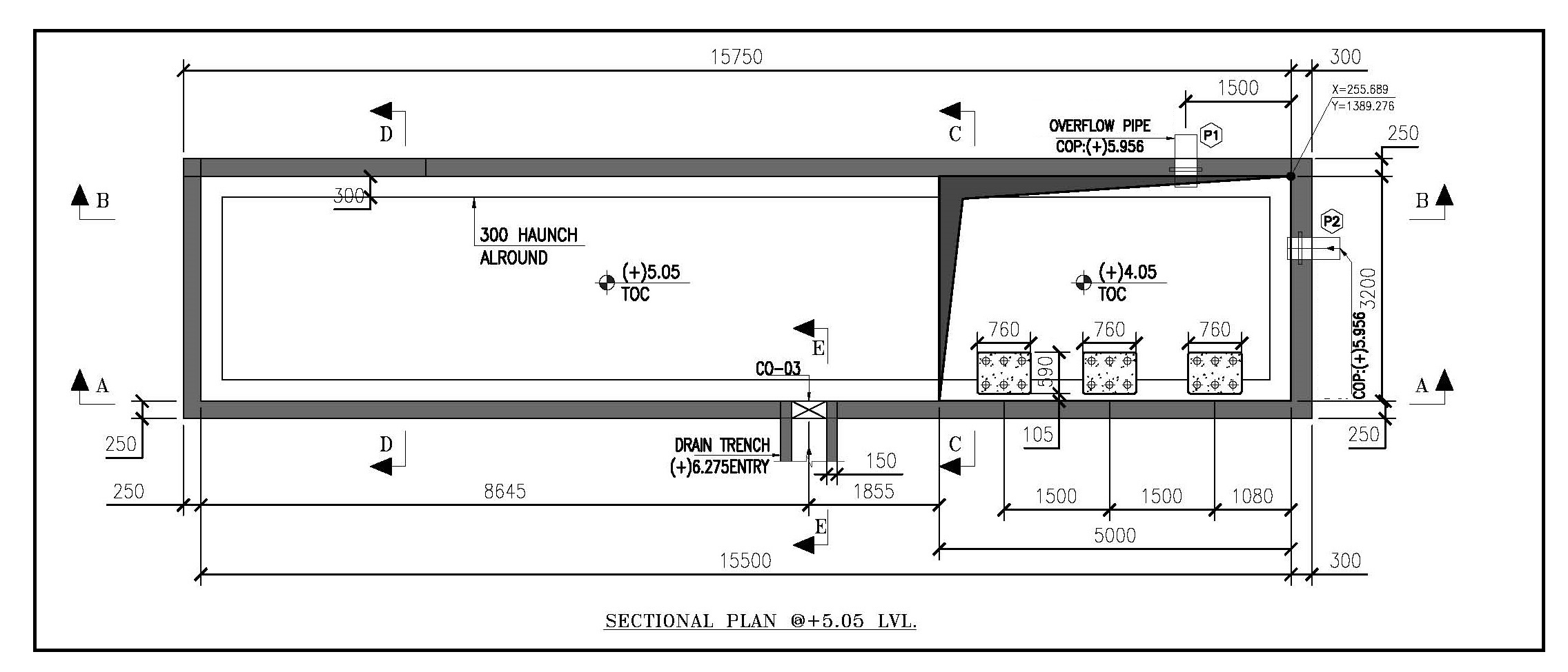
3. Draw Plan View
Include:
- Overall sump dimensions (L × B or Diameter)
- Inlet pipe location and invert levels
- Outlet pipe and pump delivery points
- Partition wall (if twin compartment)
- Cable tray and pump discharge header
- Maintenance platform
- Vent pipe arrangement
4. Draw Sectional Views
At least 2 sections:
- Longitudinal section
- Invert levels
- Bottom slab, sump bottom slope
- Freeboard height
- Pump suction pipe
- Cross section
- Wall thickness
- Reinforcement details
- PCC and raft slab
- Earth backfill details
5. Show Reinforcement Details
- Raft slab main & distribution bars
- Wall vertical & horizontal bars
- Starter bars and lap lengths
- Key plan for bar descriptions
6. Add Structural Details
- Concrete grade (M25 typical)
- Steel grade (Fe500)
- Water proofing notes
- Construction joints
- Anti-floatation key (if needed)
7. Pump and Accessories Layout
- Guide rails and pump lowering system
- Pump stand
- Cable support hooks
- Pressure gauge + NRV + Gate Valve
- Level switches (LL, L, H, HH)
- Float switches or ultrasonic level sensors
8. Notes & Specifications
Include:
- General notes
- IS code references (e.g. IS 456, IS 3370)
- Safety ladder material & spacing
- Clear cover
- Backfilling material
- Grouting instructions
9. Title Block
- Drawing title: Collection Sump Pit – GA / Structural / Reinforcement Drawing
- Project name
- Scale
- North direction (plan view)
- Prepared by / Checked by / Approved by
- Revision history
✅ Final Drawing Set May Include:
| Drawing Type | Purpose |
|---|---|
| GA Plan & Section | Layout and dimensions |
| Structural Drawing | Slab & wall design |
| Reinforcement Details | Bar details |
| Piping & Pump Layout | MEP details |
| Bill of Quantities (BOQ) | Material summary |
Related Posts:
One response to “Sump Pit Drawing”
Simply wanna input that you have a very decent internet site, I enjoy the layout it really stands out.