
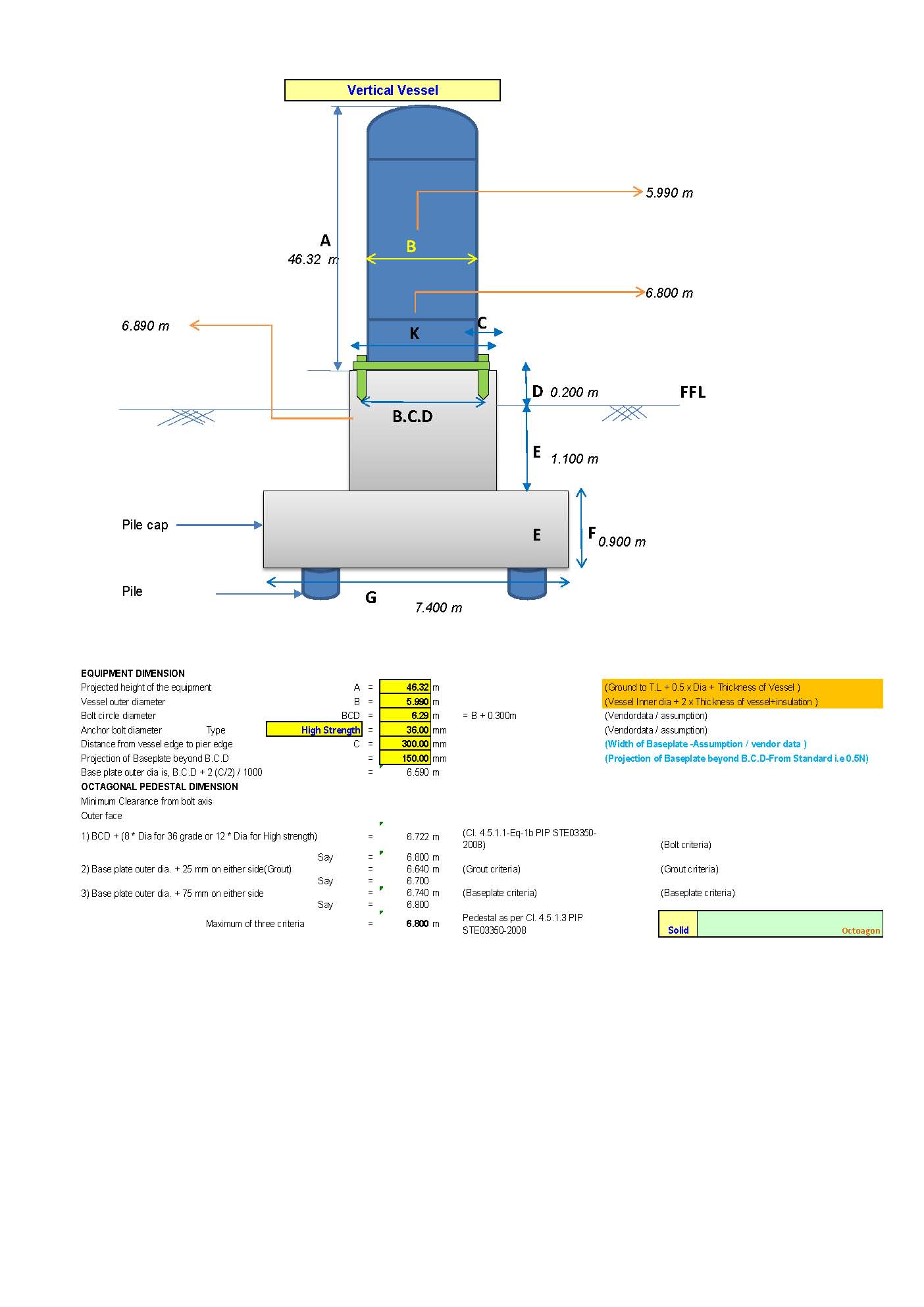
Vertical Vessel foundation design
The design of a foundation for a vertical vessel involves ensuring the stability, strength, and serviceability of the foundation under various loads (dead load, live load, wind, seismic, etc.). Vertical vessels are typically supported on circular ring foundations, annular plates, or pedestal-type foundations.
Here’s a step-by-step process for designing a vertical vessel foundation:

Input Data
Load Details:
- Dead Load (Wd): Weight of the vessel, including self-weight, insulation, and accessories.
- Live Load (Wl): Load due to operational conditions (e.g., liquid or gas weight inside the vessel).
- Wind Load (Ww): Calculate as per IS 875 (Part 3).
- Seismic Load (Ws): Calculate as per IS 1893.
- Other Loads:
- Pipe connections.
- Thermal expansion forces.
Foundation Details:
- Type of soil: Safe bearing capacity (SBC), cohesion (ccc), and angle of internal friction (ϕ\phiϕ).
- Depth of foundation: Minimum depth to avoid frost or scour.
Material Properties:
- Concrete grade: Typically M25 or higher.
- Steel grade: Fe 415 or Fe 500.
2. Types of Vertical Vessel Foundations
- Ring Foundation:
- Common for tall vessels.
- Designed as a combination of circular footing and a pedestal.
- Rectangular or Square Foundation:
- Used for smaller vessels or where site constraints exist.
- Piled Foundation:
- Used for poor soil conditions or when the vessel imposes high loads.
3. Load Combinations
Design loads are based on factored combinations as per IS 456:2000:
- Gravity Load Combination: 1.5 ⋅ (Wd+Wl)
- Gravity + Wind Combination: 1.5 ⋅ (Wd+Wl+Ww)
- Gravity + Seismic Combination: 1.2 ⋅ (Wd+Wl+Ws)
Stability Checks
- Overturning Moment: Calculate overturning due to lateral loads (wind or seismic):
Mo = Ww ⋅ H + Ws ⋅ H
Ensure the resisting moment (Mr) satisfies:
Mr ≥ 1.5 ⋅ Mo
- Sliding: Check sliding resistance at the base:
Rs= c ⋅ A + Wv ⋅ tan(ϕ)
Where:
-
- Rs: Sliding resistance.
- A Area of the base.
- Wv: Vertical load on the foundation.
Ensure:
Rs ≥ 1.5 ⋅ Fh
Where Fh is the horizontal load (wind/seismic).
- Bearing Capacity: Verify that the net pressure under the foundation does not exceed the SBC:
Qnet = Wtotal / A
Structural Design
Base Area:
- Required base area:
A=Wtotal / SBC
- Select dimensions based on area and shape (circular, square, or rectangular).
Reinforcement Design:
- For Base Slab:
- Calculate bending moment due to vertical and lateral loads.
- Provide main reinforcement in the bottom and distribution reinforcement in the top.
- For Pedestal:
- Design the pedestal for axial and lateral loads.
- Provide vertical reinforcement (As) and ties for confinement.
Anchor Bolt Design:
- Calculate tension due to overturning moments: T = Mo / r Where r is the distance from the bolt to the center of the pedestal.
- Check for pullout resistance and shear capacity of the anchor bolts.


- 3D HOUSE DESIGN (19)
- Civil and Structural Design Calculations (41)
- Commercial Plans (9)
- East Facing House Plans (14)
- Engineering Concepts – Civil & Structural (155)
- Excel Spreadsheets (18)
- Free Downloads (17)
- House Plans (51)
- Industrial standards (69)
- North Facing House Plans (15)
- South Facing House Plans (12)
- West Facing House Plans (7)