
Padeye is a plate or attachment point commonly used in lifting and rigging operations to connect slings, shackles, or other lifting equipment. Proper design and calculation of a padeye are essential to ensure safe lifting operations. The calculation is based on factors such as load capacity, thickness of the plate, material properties, and hole size for the shackle.
Steps for Padeye Design and Calculation
- Load Determination:
- Design Load (P): Determine the load to be lifted, considering the dynamic factors. If a dynamic load factor (DLF) is required, multiply the static load by the DLF.
- Load Angles: Determine the loading angle (θ) and ensure that any out-of-plane loading is accounted for.
- Load Type: Consider whether the load is applied vertically or at an angle, which will impact the stresses on the padeye.
- Material Selection:
- Select an appropriate material for the padeye, such as steel (e.g., ASTM A36 or ASTM A572).
- Identify the material’s yield strength (fyf_yfy) and ultimate strength (fuf_ufu).
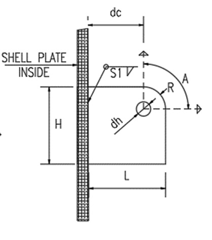
- Padeye Geometry:
- Thickness (t): Typically, the padeye plate thickness should be sufficient to resist the applied stresses. The thickness can be increased based on the load and the material’s strength.
- Hole Diameter (d_h): The hole should accommodate the shackle pin, with the diameter being slightly larger than the pin size.
- Padeye Length (L): The distance from the center of the hole to the edge of the padeye should be long enough to avoid tearing and stress concentration.
Padeye Width (W): The width of the padeye should be adequate to resist bending and shear stresses.

- Padeye Stress Calculation:
- a) Tension Stress:
The tensile stress (σt) on the padeye plate is calculated using: σt=P/ t×W
Where:
- P = Design load
- t = Padeye thickness
- W= Width of the padeye
Ensure that the tensile stress is less than the yield strength of the material (fy).
- b) Bearing Stress:
The bearing stress (σb) around the hole (where the shackle pin is placed) is: σb=P\dh×tP Where:
- P = Load applied
- dh = Hole diameter
- t = Thickness of the padeye plate
The bearing stress should be checked against the allowable bearing stress for the material.
- c) Shear Stress:
The shear stress (τ) on the padeye is calculated as: τ=P/ 2×t×W
Where:
- P = Applied load
- t = Thickness of the padeye plate
- W = Width of the padeye
Shear stress should be less than the allowable shear strength of the material, typically 0.6fy
- d) Bending Stress:
For a padeye subjected to bending due to out-of-plane loading or eccentric loading, the bending stress (σb ) can be calculated using: σb=M / S
Where:
- M = Bending moment
- S = Section modulus of the padeye cross-section
Ensure that the bending stress does not exceed the allowable stress of the material.
- Check Against Failure Modes:
- Tensile failure: Ensure that the tensile stress does not exceed the allowable tensile stress of the material.
- Bearing failure: Ensure that the bearing stress at the hole does not exceed the material’s bearing capacity.
- Shear failure: Check that the padeye can resist shear forces.
- Bending failure: If there is eccentric loading, check that the bending stresses are within safe limits.
- Tear-out failure: Ensure the distance from the hole to the edge of the plate is sufficient to prevent tear-out.
- Safety Factor:
Apply a safety factor to the design to account for uncertainties in load estimation, material strength, and fabrication quality. A common safety factor for padeyes is 1.5 to 3, depending on the application.
- Weld Strength (if applicable):
If the padeye is welded to a structure, ensure that the welds are designed to handle the applied loads. Check both the throat size and the length of the weld.
Conclusion:
The design of a padeye requires careful consideration of material strength, geometry, and load application. The stresses (tensile, shear, and bearing) must be checked, and the design must meet the required safety factors. Accurate calculation ensures the padeye can handle the lifting operation without failure.
Example Calculation:
- Load (P): = 50 kN
- Material: Steel with yield strength fy= 250 Mpa
- Padeye thickness (t): = 20 mm
- Hole diameter (d_h): = 25 mm
- Padeye width (W): = 100 mm
- Tension Stress:
σt = 50,000 / 20×100 =25 MPa
(Tensile stress is less than fy).
- Bearing Stress:
σb =50,000 / 25×20 =100 MPa
(Check against allowable bearing stress).
- Shear Stress:
τ = 50,000 / 2×20×100=12.5 MPa
(Shear stress is within limits).
By following these steps and performing necessary calculations, the Padeye design will ensure safe and efficient lifting operations

Categories
- 3D HOUSE DESIGN (34)
- Civil and Structural Design Calculations (76)
- Commercial Plans (9)
- East Facing House Plans (14)
- Engineering Concepts – Civil & Structural (225)
- Excel Spreadsheets (37)
- Free Downloads (49)
- House Plans (57)
- Industrial standards (92)
- North Facing House Plans (15)
- South Facing House Plans (15)
- West Facing House Plans (9)
Recent Posts
- Manhole Types and Details
- Catch Basin Types and Details
- Eurocode Base Plate Calculator – EN 1993-1-8
- Base Plate Design Calculation AS 4100
- Base Plate Design Calculator CSA A23.3
- Base Plate Design Calculator ACI 318
- Base Plate Design as per IS 800 2007
- East Facing 38×56 House Plan – Ground & First Floor Design with 3BHK + Home Theatre
- Foundation Detail Drawings for Buildings With CAD Files
- Bar Bending Schedule | BBS Calculator For Beam Column and Slab
- Room Paint Calculator | Paint, Primer & Putty Quantity & Cost Estimator
- Load Conversion & Stress Calculator | kN to kg, ton, N, MPa Online
- Water Tank Capacity Calculator – Feet & Meter Conversion (Litres & Gallons)
- Brick Wall Construction Calculator | Calculate Bricks & Cost Instantly |
- Unit Converter – Feet, Inches, cm, mm, Yard to Meter and Vice Versa
- Lifting Analysis of Skid Using Spreader Beam 4-Point
- Base Plate Design as per IS Code | IS 800:2007 Steel Column Base |
- Laser Cut Railing Price in India 2025 | MS & SS CNC Balcony Designs
- MS Balcony Railing Price in India 2026 | Mild Steel Railing Works |
- Stainless Steel with Glass Handrail Price 2026
- Modern Duplex House West Facing 36 x 48
- Pooja Room Door Design
- Modern House 3D Design – Visualizing Your Dream Home
- Balcony Railing Designs for Modern Homes
- Civil Engineering Interview Questions and Important Practical Foundation
- Wind Load Calculation IS 875 Part 3 2015
- Front Elevation Design for Modern Homes
- Road Turning Radius as per IS/IRC Codes and International Standards AASHTO BS/DMRB
- Foundation Design ACI 318 pdf & Excel Download
- Steel Staircase Design
- Front Elevation 20×60 House
- Steel Shed with Mezzanine Floor
- Structural Masonry Designers Manual
- Water Supply Piping Plan and Plumbing Schematic Diagram
- Sump Pit Drawing
- Design of Steel Silo
- Design of Beam to Beam End Plate Connection
- DESIGN OF FLAT SLAB pdf Free Download
- Design of Thrust Block
- Cage Ladder Detail Standard Drawing pdf Free Download
- DESIGN OF BARREL FOR BOX CULVERT pdf Free Download
- Design of Retaining Wall Calculation pdf Free Download
- Analysis and Design of Drain Sump Pit
- Design of High Rise Buildings as per Eurocode
- Design of Steel Shelter as per IS 800
- Octagonal Pedestal Design
- Ring Wall Foundation Design
- Decking Sheet with Concrete – Design Details & Specifications
- Hydrodynamic Load on Tanks | Convective and Impulsive |
- PILE STIFFNESS CALCULATION