
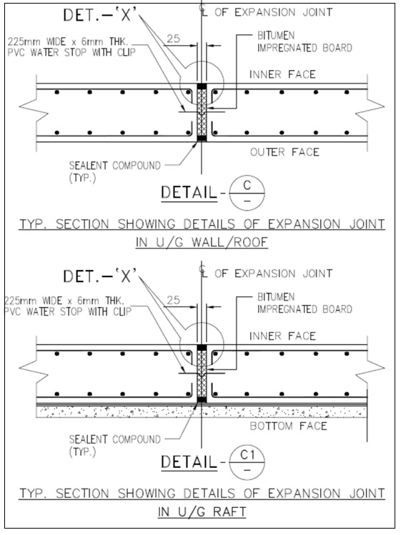
EXPANSION JOINTS SHALL BE PROVIDED AT LOCATIONS AS SHOWN IN THE DRAWING. ALL REINFORCEMENT SHALL BE TERMINATED BEFORE THE JOINT. ALL UNDER GROUND EXPANSION JOINTS SHALL BE ARTICULATED AS SHOWN IN DETATIL- C & DETAIL- C1.
Joint Width: Usually ranges from 20 mm to 50 mm, depending on the total length and expected movement.
Joint Filler Material: Compressible, resilient material like:
- Bitumen impregnated fiber board
- Closed-cell foam
- Cork or neoprene
Sealant: Applied on top to make the joint waterproof:
- Polysulfide
- Polyurethane
- Silicone sealants


Water Barrier (optional): Water bar (PVC/rubber) embedded in slab or wall construction to prevent seepage.
Edge Protection (optional):
- Aluminum or stainless steel angle or cover strip for protection.
Fire Barrier (for buildings): Fire-resistant material like mineral wool with intumescent sealant.
Reference Standards
- IS 3414: Code of Practice for Design and Installation of Joints in Buildings
- IS 456: Code of Practice for Plain and Reinforced Concrete
- IRC SP 87: For bridges and highways
🧾 Specification for Expansion Joint (Civil/Structural Projects)
1. Purpose
To accommodate movement due to thermal expansion/contraction, shrinkage, settlement, or seismic activity, and to prevent stress concentration and cracking in concrete structures.
2. Location of Expansion Joints
- For RCC framed structures: at intervals of 45 to 60 meters (as per IS 3414 & IS 456).
- In bridges: at 10 to 30 meter intervals, depending on span and expansion coefficient.
- In pavements: every 4.5 to 6 meters.
- At junctions of different construction phases or materials.
3. Components and Materials
| Component | Material & Properties |
|---|---|
| Joint Filler Board | Bitumen impregnated fiberboard conforming to IS 1838 – 12 mm to 25 mm thick |
| Sealant (Top) | Polysulphide / Polyurethane / Silicone sealant, flexible, UV resistant |
| Bond Breaker Tape | Polyethylene tape to prevent three-side adhesion |
| Backing Rod | Closed-cell polyethylene foam rod (compressible) |
| Water Barrier | PVC/rubber waterstop (minimum 150 mm width) as per IS 12200 |
| Edge Protection | Galvanized steel, aluminum, or stainless steel cover plates (for surface or heavy traffic) |
| Fire Barrier (optional) | Mineral wool with intumescent sealant, fire rating minimum 2 hours |
4. Joint Dimensions
- Joint width: 20 mm to 50 mm (depending on expected movement and temperature variation)
- Depth: Equal to structural member depth (slab/beam thickness)
- Sealant depth: 10 to 20 mm (as per manufacturer’s recommendation)
5. Installation Procedure
- Place formwork and cast adjacent sections with joint gap.
- Fix joint filler board vertically aligned in joint location.
- Clean joint faces, place bond breaker tape and backing rod.
- Apply primer (if required) and install sealant over the top.
- Place water bar at mid-depth of joint (for slabs, retaining walls).
- For exposed joints, fix metal cover plates using anchor bolts or countersunk screws.
6. Performance Requirements
- Accommodate ±10% to ±25% movement.
- Resistance to UV rays, weathering, and chemicals.
- Water-tight, dust-tight, and crack-resistant.
- Service life: minimum 15–25 years depending on environment.
7. Standards and Codes
- IS 3414: Code of Practice for Design and Installation of Joints in Buildings
- IS 456: Code of Practice for Plain and Reinforced Concrete
- IS 1838: Specification for Fiberboard for Expansion Joints
- ASTM D1751: Bituminous fiberboard for expansion joints
- IRC:SP:87 – Guidelines for Design and Installation of Expansion Joints in Bridges