
Designing a crane girder, which is a key structural component used in overhead cranes, involves careful consideration of loads, material properties, structural analysis, and adherence to relevant standards and codes. Here’s a step-by-step guide on how to design a crane girder
Step 1: Determine Design Parameters
- Crane Capacity:
- Determine the lifting capacity of the crane (e.g., 5 tons).
- Span of the Girder:
- Determine the distance between the supports of the girder, which is the span.
- Crane Type:
- Identify the type of crane (e.g., single-girder or double-girder overhead crane).
- Operating Conditions:
- Consider the environment (indoor/outdoor, temperature, corrosive conditions) and the frequency of operation.
- Codes and Standards:
- Refer to relevant standards like ASME B30.2, CMAA (Crane Manufacturers Association of America) Specification No. 70, DIN 15018, or local codes for design criteria.
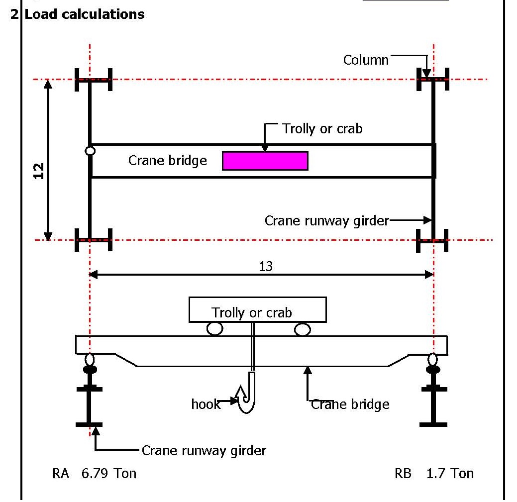
Step 2: Calculate Loads
- Dead Load (DL):
- Include the weight of the girder itself and any permanent attachments (e.g., rails, electrical components).
- Live Load (LL):
- Calculate the weight of the crane, trolley, and the maximum load the crane will lift (crane capacity).
- Impact Load (IL):
- Consider impact factors (e.g., 25% of the crane capacity for standard cranes) to account for dynamic effects during lifting and moving.
- Lateral Loads:
- Consider lateral forces due to the crane’s operation, particularly if there is any side loading.
- Wind and Seismic Loads:
- Include wind loads if the crane is located outdoors and seismic loads based on the geographic location.
Step 3: Select Material
- Steel Grade:
- Choose the appropriate grade of structural steel for the girder (e.g., ASTM A36, A572).
- Material Properties:
- Consider yield strength, ultimate tensile strength, and elasticity modulus.
Step 4: Preliminary Sizing
- Girder Section:
- Select an initial section for the girder, typically an I-beam or box girder, based on rough calculations of bending stress and deflection.
- Bending Moment (M):
- Calculate the maximum bending moment using: M=W⋅L/8
- Where WWW is the total load (including DL, LL, IL), and LLL is the span.
- Section Modulus (S):
- Estimate the required section modulus: S=M/ σallow
- Where σallow is the allowable stress in the material.
- Deflection:
- Ensure that the deflection of the girder under load is within permissible limits (usually L/750 for cranes).
Step 5: Detailed Design
- Shear Force (V):
- Calculate the maximum shear force at the supports: V=W/2
- Check Shear Stress:
- Verify that the shear stress in the girder does not exceed the allowable shear stress.
- Torsional Analysis:
- For asymmetric loads or loads offset from the center, consider torsional effects and ensure the girder can resist them.
- Web and Flange Design:
- Ensure the web is thick enough to resist buckling, and the flanges are sized to handle bending moments.
- Buckling Check:
- Check for both local buckling of the web and global buckling of the girder.
Step 6: Connections and Detailing
- End Connections:
- Design the connections between the girder and the supporting structures, considering bolted or welded joints.
- Stiffeners:
- Add stiffeners at points of concentrated loads, such as where the trolley wheels contact the girder.
- Camber:
- Consider adding camber (a slight upward curve) to the girder to compensate for deflection under load.
Step 7: Verification and Analysis
- Finite Element Analysis (FEA):
- Perform FEA to verify the stress distribution, deflection, and stability of the girder.
- Compliance Check:
- Ensure that the design meets all relevant codes, safety factors, and operational requirements.
- Design Optimization:
- Optimize the design by adjusting the girder size, material, or other parameters to achieve a balance between safety, cost, and performance.
Step 8: Prepare Drawings and Documentation
- Technical Drawings:
- Create detailed drawings of the girder, including all dimensions, material specifications, and connection details.
- Calculation Report:
- Document all calculations, assumptions, and analysis results for review and approval.
- Bill of Materials:
- Prepare a list of materials needed for fabrication.
Conclusion
Designing a crane girder requires a thorough understanding of structural principles, dynamic loading conditions, and material properties. By following the steps outlined above and adhering to industry standards, you can ensure that the crane girder is safe, efficient, and fit for its intended purpose. For complex designs, consulting with a structural engineer or using specialized design software may be necessary


Crab (Trolley) Weight for 5-Ton Capacity
- Overhead (EOT) Crane:
- The weight of an Electric Overhead Traveling (EOT) crane with a 5-ton capacity can range from 2,000 kg to 5,000 kg (approximately 2 to 5 tons). This range depends on the span of the crane, the type of girder (single or double), and the materials used in the crane’s construction.
- Gantry Crane:
- A 5-ton gantry crane, which is a type of crane with legs instead of being mounted on a building structure, can weigh between 3,000 kg to 7,000 kg (approximately 3 to 7 tons). The weight can vary significantly based on the height and span of the gantry.
- Jib Crane:
- A 5-ton jib crane, which has a horizontal jib or arm that supports a movable hoist, might weigh between 1,500 kg to 4,000 kg (approximately 1.5 to 4 tons), depending on the length of the jib and the design.
Crab Weight:
The crab or trolley for a 5-ton capacity crane generally weighs between 500 kg to 1,500 kg (approximately 0.5 to 1.5 tons). The exact weight depends on the design, materials used, and additional features like motors, controls, and the type of hoist (manual, electric, or hydraulic).
Summary of Estimated Weights
Crab/Trolley: 500 kg to 1,500 kg
EOT Crane (5-ton capacity): 2,000 kg to 5,000 kg
Gantry Crane (5-ton capacity): 3,000 kg to 7,000 kg
Jib Crane (5-ton capacity): 1,500 kg to 4,000 kg