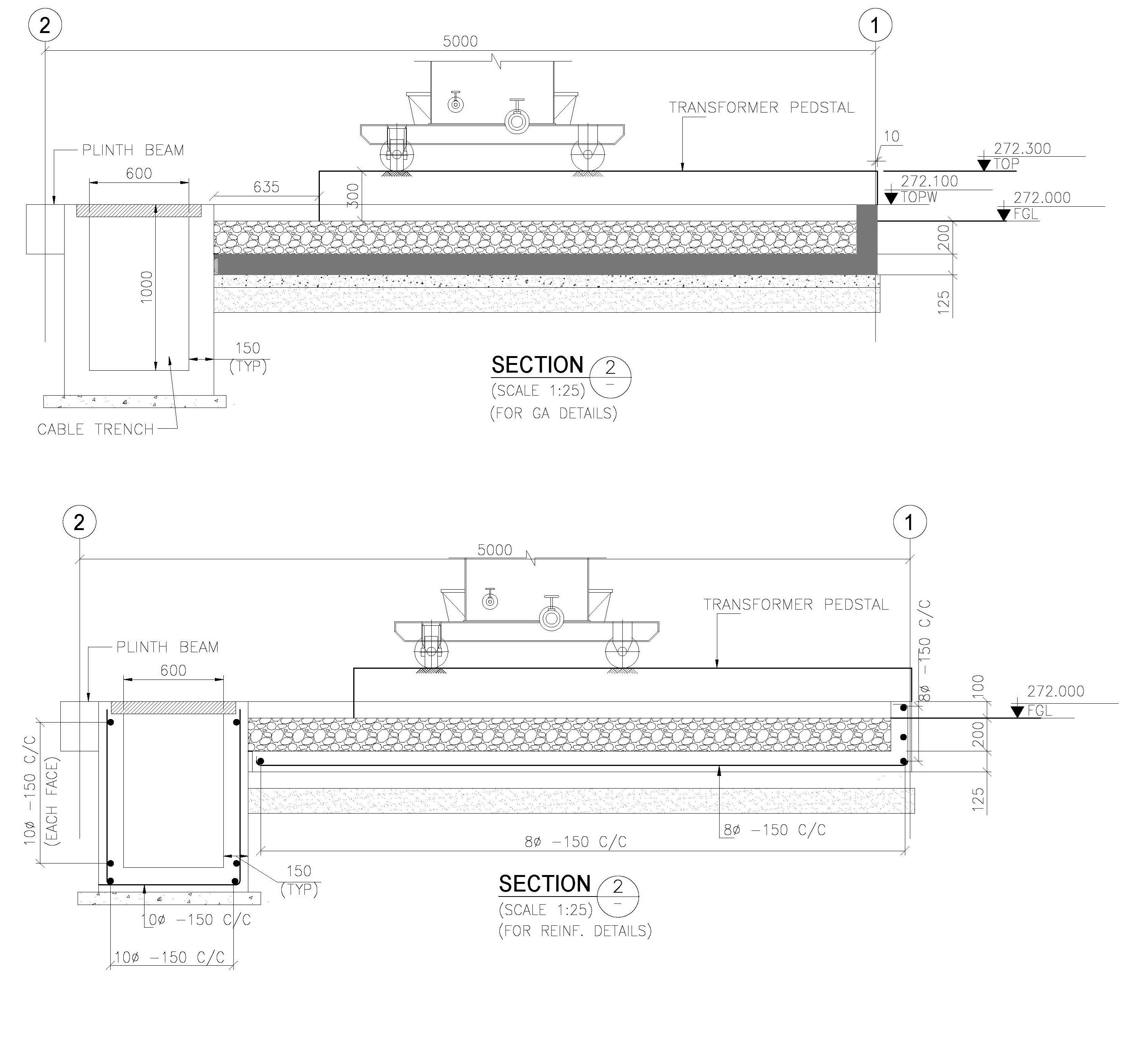
A transformer foundation with a soak pit is designed to support the weight of the transformer, distribute loads evenly, and provide an oil containment system in case of leakage. The soak pit ensures safe disposal of transformer oil, preventing environmental contamination.
1. Purpose of Transformer Foundation with Soak Pit
✔️ Provides a stable and vibration-free base for the transformer.
✔️ Ensures load-bearing capacity to support transformer weight.
✔️ Prevents oil spillage hazards by containing transformer oil leaks.
✔️ Complies with electrical safety and environmental standards.
✔️ Facilitates proper drainage and fire protection measures.


2. Components of Transformer Foundation with Soak Pit
| Component | Purpose |
|---|---|
| Reinforced Concrete (RCC) Foundation | Supports transformer load and prevents settlement |
| Gravel Bed | Provides drainage and prevents oil stagnation |
| Oil Collection Pit (Soak Pit) | Collects transformer oil leaks and prevents soil contamination |
| Cable Trenches | Houses power cables, earthing strips, and control wiring |
| Earthing System | Ensures proper grounding to prevent electrical hazards |
| Fire Protection System | Prevents fire hazards due to oil spillage |
| Fencing & Security | Prevents unauthorized access |
3. Design Considerations for Transformer Foundation
a. Load Capacity & Structural Design
- The foundation should withstand static and dynamic loads of the transformer.
- Load-bearing capacity must comply with IS 1678, IS 456, IS 1893, and IEEE 980 standards.
- Concrete Grade: Minimum M25 or higher for structural strength.
- Foundation Thickness: Depends on the weight of the transformer, typically 300mm to 600mm RCC slab.
- Reinforcement: Fe500 steel bars as per IS 456.
b. Transformer Foundation Dimensions
| Transformer Capacity (MVA) | Foundation Size (L × W) (mm) | Slab Thickness (mm) |
|---|---|---|
| 1-5 MVA | 2000 × 1500 | 300 |
| 5-10 MVA | 3000 × 2500 | 400 |
| 10-25 MVA | 4000 × 3500 | 500 |
| 25-50 MVA | 6000 × 4500 | 600 |
4. Soak Pit Design for Transformer Oil Collection
a. Purpose of Soak Pit
- Collects oil leaks or spills from the transformer.
- Prevents soil and groundwater contamination.
- Acts as a fire protection measure by limiting oil spread.
b. Soak Pit Design Parameters
- Soak Pit Size: Based on transformer oil volume (usually 3m × 3m × 1.5m).
- Depth: 1000mm to 1500mm, depending on site conditions.
- Construction: Brick masonry or RCC walls with oil-resistant lining.
- Filter Layers:
- Top Layer: 150mm gravel (40mm size)
- Middle Layer: 300mm coarse sand
- Bottom Layer: 200mm crushed stone
c. Soak Pit Layout
- Positioned below the transformer radiator area.
- Connected to a drain pipe leading to an oil collection chamber.
- Fire-resistant mesh cover to prevent debris accumulation.
5. Electrical & Safety Requirements
a. Earthing System for Transformer Foundation
- Neutral Earthing: 2-3 earthing pits connected to the neutral point.
- Body Earthing: Separate grounding system for transformer body.
- Earth Resistance: Must be < 1 ohm (IS 3043 standard).
- Earthing Strip: GI or copper strips (75mm × 12mm) connected to ground grid.
b. Fire Protection & Safety Measures
- Fire-resistant barriers (RCC walls or sand trenches).
- Oil spill containment trench connected to soak pit.
- Fire extinguishers & foam systems near transformer area.
- Minimum clearance distances as per IS 10028 & IEEE standards.
c. Cable Trench Requirements
- Depth: 600mm – 1000mm (depending on voltage level).
- Cable Trench Cover: Precast RCC slab or chequered plate.
- Separation from Foundation: Minimum 300mm gap between trench and foundation.
6. Typical Transformer Foundation & Soak Pit Layout
Key Components in Layout Drawing
- Transformer Base Slab with anchor bolts.
- Soak Pit with filter layers and oil containment drain.
- Cable Trenches for power, control, and earthing cables.
- Fencing and Fire Safety Features.
- Earthing Grid Layout with ground rods and strips.
7. Construction & Installation Guidelines
✔ Ensure proper compaction of soil before RCC slab casting.
✔ Provide slope (1:50) for oil drainage towards soak pit.
✔ Use non-absorbent fire-resistant materials for oil containment.
✔ Allow curing time (14-28 days) before transformer installation.
✔ Inspect for leaks and cracks before commissioning.
8. Compliance with Standards & Codes
| Standard | Description |
|---|---|
| IS 1678 | Transformer foundation design |
| IS 456 | RCC design for foundations |
| IS 10028 | Installation & maintenance of transformers |
| IS 3043 | Earthing system requirements |
| IEEE 980 | Oil containment systems |
| NFPA 70 | Electrical safety & fire prevention |
9. Conclusion
A well-designed transformer foundation with a soak pit ensures structural stability, safety, and environmental protection. By following proper specifications, earthing, drainage, and fire protection measures, you can enhance transformer longevity and operational efficiency.
- Column Buckling

- Moody Chart | Moment Reactions for Rectangular Plates |

- Standard Road Details

- DG Building Architectural Plan & Finishing Schedule

- Technical Details for Wash Basin Section and Elevation

- Tender Technical Specification for Plumbing and Sanitary works

- Fencing Gate Details and Requirements

- Fencing Layout and Details For Transformer Area

- Fencing with Angle Post and Pipe Post Details & Arrangements

- Civil Engineering Formula Book | Pocket Guide pdf Free download |

- Transformer Foundation with Soak Pit Layout and Details

- Grating Standard Details and Specifications

- Chequered Plate Standard Details

- Handrail Details for Steel Structural Floors

- Cable Pull Pit Requirements and Details

- Laboratory Building Plan and Architecture Details

- Structural Bolt Details Types Grades and Applications

- Finishing Schedule Drawing for Doors, Windows, and Rolling Shutters

- Workshop Building Architectural Layout

- Calculation of Foundation Bearing Capacity as per IS 6403 – 1981

- Terzaghi’s Bearing Capacity Calculation For Foundations

- DESIGN AND CONSTRUCTION METHOD OF MULTISTORY CONCRETE BUILDINGS

- Civil Structural Engineering Interview Questions pdf Free Download

- Civil Structural Engineering Interview Questions

- SHEAR FORCE AND BENDING MOMENT DIAGRAMS WITH FORMULA


